
Ball splines are often lumped into the category of recirculating linear bearing guides (aka linear bushings), but they offer functionality beyond that of traditional linear bushings. Standard ball splines provide both linear motion and torque transmission, while rotary ball splines combine linear and rotary motion in one device.
Ball splines for torque transfer
A ball spline is essentially a linear bushing and shaft system, with axial grooves both along the shaft and along the inner diameter of the nut (hence, the term “spline”). Load-carrying balls recirculate within the nut, much the same way as in a linear bushing. The grooves in the shaft, however, prevent rotation and facilitate the transmission of torque. This allows ball splines to withstand overhung loads and moment loads, unlike linear bushings, which can only support radial loads.

Image credit: THK Co., Ltd.
In a ball spline assembly, the part that houses the recirculating balls is referred to as a nut, rather than a bushing, although its functionality is different from that of a recirculating ball nut.
Because the design of a ball spline affords much greater contact area between the balls and the grooves than that of standard bushings, ball splines have significantly higher load capacities. Ball splines typically have two, three or four grooves, although some designs have up to six grooves. Like the raceways of profiled rail bearings, the grooves in a ball spline can be designed with either circular arc geometry, which provides two-point contact on each ball, or Gothic arch geometry, which provides four-point contact on each ball.
Gothic arch geometry provides higher rigidity, but also contributes to higher friction, while the circular arc geometry has lower friction and smoother running characteristics. Torque capacity is determined by the number of contact points, so a ball spline with four Gothic arch grooves will have 16 contact points and transmit more torque than one with two Gothic arch grooves, having just 8 contact points.
Sizing and selection of ball splines combines technical considerations from both linear recirculating bearings and ball screws. Life is calculated via the standard bearing life equation, using both radial loads and torque loads. Like profiled rail guides, ball splines can be preloaded to increase rigidity and provide better support for moment loads.
Ball splines are fixed with rotary bearings, much like ball screws, and the end fixity (fixed-fixed, fixed-floating, etc.) plays a factor in determining critical speed, as do the shaft root diameter and unsupported length. Accuracy grades are also assigned similarly to those of ball screws, based on radial run-out and perpendicularity of the shaft ends, radial run-out of the nut body, and perpendicularity of the nut flange (when applicable). However, ball spline accuracy classes are not based on industry standards such as DIN or JIS, so one manufacturer’s “precision” accuracy may be similar to another manufacturer’s “high” accuracy.
Rotary ball splines for combined linear and rotary motion
Image credit: NB Corporation of America
While recirculating linear bearings provide linear motion and ball screws provide rotary motion, rotary ball splines fill the gap between the two, generating both linear and rotary motion.
Rotary ball splines incorporate a rotating element—angular contact ball bearings, crossed rollers, or gears—on the outer diameter of the nut. This provides rotary motion in addition to the linear motion of the ball spline itself.
Both standard and rotary ball splines are offered with a hollow spline shaft, which helps with integration into systems such as SCARA robots, allowing electrical or pneumatic lines to be routed through the spline shaft. In fact, one of the most common applications for rotary ball splines is the Z-theta axis of SCARA robots.
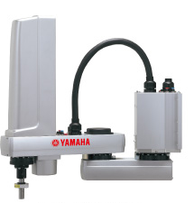
Image credit: Yamaha Motor Co., Ltd.
Feature image credit: NB Corporation of America

Leave a Reply
You must be logged in to post a comment.