
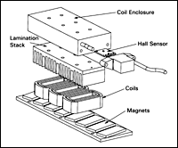
Linear motors are often classified as either ironless or iron core, referring to how their primary parts are constructed. Ironless linear motors have a primary made of windings that are embedded in epoxy resin. In iron core linear motors, the windings are mounted in an iron lamination stack.
Like the rotor and stator of a standard rotary motor, linear motors have a primary part, which contains windings, and a secondary part made of magnets. The design of the primary part is the main differentiating factor between ironless and iron core linear motors.
For both motor types, the number and length of the windings determine how much force the motor can produce, based on the magnetic attraction between the iron of the primary and the permanent magnets of the secondary, plus the magnetic force created in the windings. Iron core motors have a force density (force per working area) up to twice that of ironless motors. This means that in order to produce a given continuous force, an ironless motor would need to be twice as large as an iron core design.
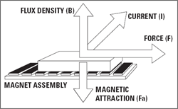
F = I x B
Image credit: Rockwell Automation, Inc.
Since ironless linear motors have a primary that’s embedded in resin, there is no magnetic attraction between the primary and secondary parts, and the forces they can produce are smaller than those produced by iron core designs. For iron core linear motors, the magnetic attraction between the iron in the primary and the permanent magnets of the secondary enables the motor to produce high forces, but this attractive force also creates cogging.
Cogging is a detent force that the motor experiences when the steel laminations of the coil cross the magnets of the secondary. This force degrades the smoothness of movement, and can be significant, making iron core motors less desirable for applications that require extremely smooth motion. However, some manufacturers have developed methods to reduce the effects of cogging, by skewing the magnets of the secondary part, which eases the change in attractive forces as the primary moves across the magnets, or by using the feedback and control system to compensate for the effects of cogging.
In addition to their ability to produce very high thrust forces, iron core motors also dissipate heat very well, thanks in part to their relatively open design with no enclosed areas. This design, however, leaves them susceptible to contamination — particularly metallic chips or flakes, which are attracted to the permanent magnets and can damage the motor. Another factor that contributes to the iron core linear motor’s good heat dissipation is the fact that their primary part is mostly made of metal (as opposed to the epoxy enclosure of an ironless design), which acts as a heat sink.
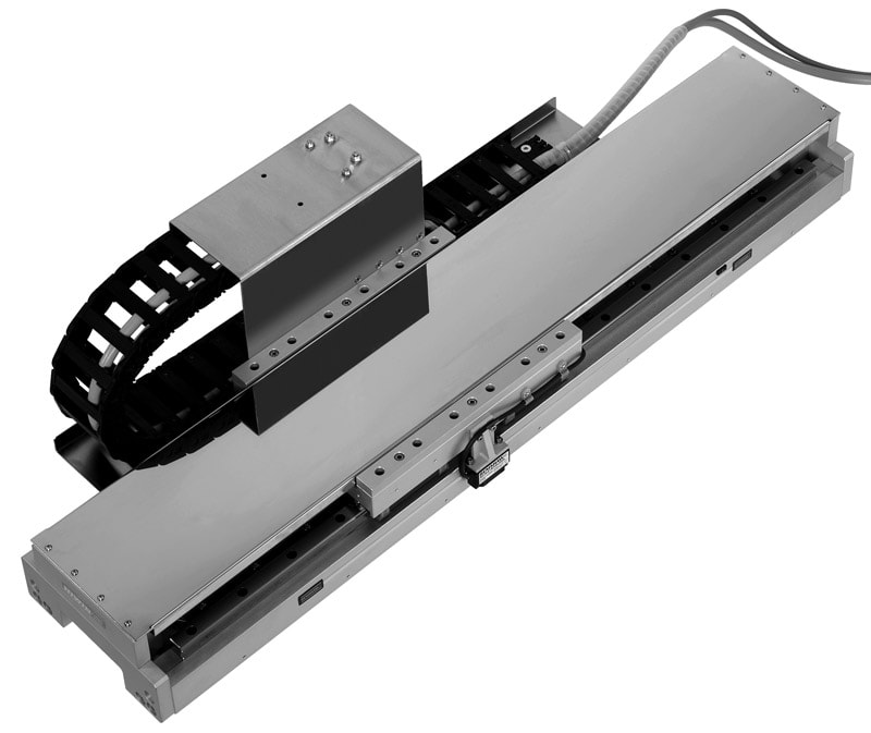
Whether ironless or iron core, linear motors are simply drive units and must include some sort of guide mechanism in order to create a working assembly. When designing a linear motor system using iron core motors, it’s important to take into account the attractive force between the primary and secondary parts in order to properly sizing the support bearings. Linear profiled rails are the most common guide systems used with linear motors, although air bearing systems are sometimes used. Since air bearings require a preload, the attractive force between the windings and the magnets is beneficial for an iron core motor using air bearing guides.
With high continuous forces and good heat dissipation, iron core linear motors are ideal for pressing, molding, and machining applications. They also excel at high-speed testing that requires the application of high forces or pressures.
Feature image credit: Aerotech Inc.

Leave a Reply
You must be logged in to post a comment.