
Piezo actuators provide highly responsive, rapid movements, but their displacement is limited to just 0.1 to 0.2 percent of the actuator length. To overcome this limited stroke capability, a piezo actuator can be combined with elements, such as flexures, that provide mechanical amplification. The amplification provided by a flexure mechanism can extend the stroke of a piezo actuator from several microns to several millimeters.
A flexure-guided piezo stage incorporates a stacked piezo actuator with mechanical linkages, similar to hinges, that amplify the actuator’s motion and provide guidance for the attached load. As the actuator expands, it “pushes” the linkages so they also deform, or flex, to produce additional motion. This deformation is elastic, so when the actuator retracts, the linkages move precisely back to their original positions. For even longer strokes, lever mechanisms can also be incorporated, providing a second level of motion amplification. However, as the amplification ratio increases, stiffness and responsiveness decrease due to the flexure mechanisms — and the addition of lever mechanisms can further reduce stiffness.
The piezo actuator and amplifying mechanisms are typically mounted within a fixed frame, which provides preload to the actuator and facilitates mounting for the external load.
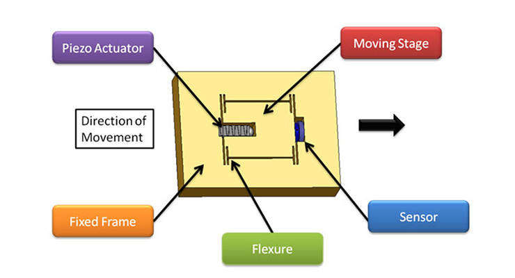
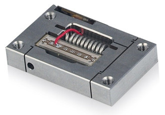
Image credit: nPoint
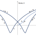
A stacked piezo actuator is one in which multiple piezo elements are layered, or stacked, on top of one another. When voltage is applied to the actuator, a strain is induced in the direction of the actuator’s polarization, causing it to expand in that direction, with the actuator’s displacement being proportional to the amount of voltage applied.
Because they rely on elastic deformation rather than friction-based rolling or sliding motion, piezo flexure stages can produce motions with nanometer-level repeatability and sub-nanometer resolution. The absence of friction also means these stages don’t experience wear or require lubrication, so particulate generation and outgassing are eliminated, making them well-suited for vacuum applications. Flexure stages can also be made from non-magnetic materials, so they can be used in applications where strong magnetic fields are present.
Piezo flexure stages are also referred to as flexure-guided piezo actuators. And some manufacturers refer to a piezo actuator with mechanical amplification as a piezo motor, so the terms “piezo flexure motor” and “flexure-guided piezo motor” are also used. In this context, the term “stage” (rather than “actuator” or “motor”) makes sense, since the flexure mechanism provides both motion amplification and guidance, with extremely flat and straight motion.
Piezo flexure mechanisms can also be constructed as two- and three-axis stages, with some multi-axis designs using the principle of parallel kinematics, in which multiple axes work together to move a single platform. Stages that use parallel kinematics have less moved mass and lower inertia than those designed with serial kinematics. They also avoid the “stacking” of errors from each axis that occurs with serial kinematic designs.
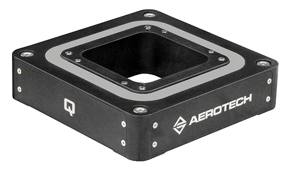
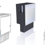
Image credit: Aerotech

Leave a Reply
You must be logged in to post a comment.