
Linear Cartesian and gantry robots are used extensively in automation, particularly for tasks such as pick and place and assembly. But for applications that require movements such as changing the orientation of a part or navigating around complex obstacles, the robot of choice is often the 6-axis articulated robot.
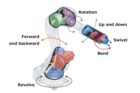
Image credit: Kawasaki
Despite their dexterity, the reach of a 6-axis robot is closely tied to the robot’s footprint and payload, making it difficult to achieve a long reach without using a correspondingly large robot. Case in point: Typical 6-axis robots have a reach of less than 1000 mm. For longer reach, the base, or pedestal, of the robot must increase accordingly to support the mass and overhung load of the robot arm and its payload. For example, a 6-axis robot with a horizontal reach of 2000 mm might require a pedestal diameter (and, therefore, floor space for mounting) in the range of 700 mm.
This limited reach can eliminate 6-axis designs from consideration in applications where they would otherwise be an ideal solution. For example, 6-axis articulated robots are well-suited for dispensing fluids or applying tapes onto objects with complex shapes. But if the object is very large, such as an automotive windshield, the size of 6-axis robot that would be needed to reach the entire surface might be prohibitive in terms of cost and footprint. Or take the case of a drilling application that requires traversing the length of an airplane wing, requiring multiple 6-axis robots to cover the entire working area.
Although many long-stroke applications can be addressed with gantry robots, operations such as those described above also require complex movements that are difficult to achieve with an end effector on a gantry robot.
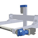
The solution for these applications is to mount the articulated robot on a robot transfer unit, which serves as a 7th axis to transport the 6-axis robot along a linear path. This extends the work envelope of the 6-axis robot and makes it possible to use one robot in applications that span long distances or multiple workstations.
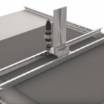
Image credit: Mesh Automation
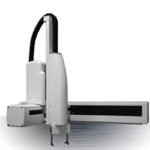
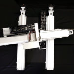
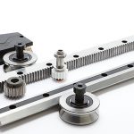
Robot transfer units can be pre-assembled linear actuators or they can be custom-built by an OEM or integrator to meet specific length, footprint, and rigidity requirements. Virtually any linear actuator type — belt, screw, rack and pinion, or linear motor — can serve as a 7th axis, although belts, rack and pinion drives, and linear motors are the most common options since they can provide the extremely long travel lengths typically required. And with linear motors and rack and pinion drives, multiple articulated robots can be mounted on one RTU and controlled independently.

Image credit: Rollon
When sizing or designing a 7th axis for an articulated robot, it’s important to remember that the transfer unit must be able to withstand the dynamic forces that result from moving the robot and its payload, as well as the static (and, in some cases, additional dynamic) forces that occur when the robot carries out its intended process — drilling, welding, fastening, or dispensing, for example. The addition of a 7th axis also presents other design considerations, such as cable management and safety of other equipment and personnel, that should be addressed.
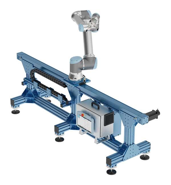
Image credit: Universal Robots
This video from Kawasaki shows how the movements of a 6-axis articulated robot mimic human movements.

Leave a Reply
You must be logged in to post a comment.