
As their name suggests, crossed roller slides (also referred to as crossed roller bearings) are linear bearings that use cylindrical rollers—as opposed to balls—to carry a load. The rollers ride between parallel guides in which v-shaped grooves have been ground. The term “crossed” refers to the fact that the rollers are arranged in a crisscross pattern; meaning that each roller is oriented at a 90 degree angle relative to the one next to it. To control their motion, the rollers are held inside a cage, similar to the caged ball or ball chain design now common in many profiled rail guides.
The cage, which can be made of resin or metal, prevents roller-to-roller contact, reducing friction and avoiding premature wear of the rollers. Resin cages allow rollers to be spaced closer together, which allows more rollers in a given stroke length and increases load capacity. While metal cages require more space and leave room for fewer rollers, they are a better solution for harsh environments or applications that take place in a cleanroom or a vacuum, since resin is less resistant to contamination and can degrade sensitive environments through outgassing.

Image credit: NB Corporation
An important consideration when using a crossed roller slide is cage creep. Because the cage floats between the guides, it can drift over time from its original position–especially in applications where the slide is mounted vertically or when the full stroke is not used. Vibrations and shock loads can also induce cage creep. When the cage is misaligned from its center position, the stroke length is reduced, and the cage will bump into an end stop when the full stroke is attempted, causing it to slide back into its centered position. Not only can this damage the slide, but it also causes the rollers to slide rather than roll, increasing friction and heat, and reducing life.
To prevent this situation, manufacturers have devised several anti-creep mechanisms. One of the most common is a rack and pinion system, either integrated into the assembly or mounted externally. Another method is the use of a studded center roller in combination with depressions along the rail that engage the studs as the slide moves. Crossed roller slides are often interchangeable between manufacturers or even with similar ball bearing slides, but it’s important to note that an anti-creep mechanism might cause the slide’s dimensions to deviate from standard sizes.
Since the rollers do not recirculate, the stroke length of cross roller slides is limited by the length of the table and the number of rollers. However, for applications that require stroke lengths less than one meter, crossed roller slides offer several advantages over recirculating linear bearings. First, the use of rollers rather than balls as the load-carrying elements provides greater load capacity, since rollers make line contact with the raceways, as opposed to the point contact of balls. This larger contact area also contributes to greater rigidity and higher accuracy.
Crossed roller bearings also avoid the oscillations and vibrations that result from bearings entering and exiting the load zone, as is the case with recirculating designs. This provides extremely smooth motion and lower noise. Because they are often used in high-precision applications, crossed roller slides are commonly manufactured with preload to eliminate clearance between the rollers and guides. Top and bottom mounting surfaces are also typically machined by the manufacturer to provide high flatness and parallelism. Therefore, cross roller slides must be mounted on a suitably rigid and flat surface.
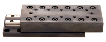
Image credit: Del-Tron Precision, Inc.
Because their rollers are arranged at 90 degree angles to each other, crossed roller slides can withstand loads in all four directions (downward, upward, and from either side). Bearing life is calculated with the same equation that is used for recirculating roller bearing guides:

With high load capacity, extremely smooth motion, and low friction, crossed roller slides are ideal for short-stroke applications that require micron- or nanometer-level positioning. Common applications include measuring equipment, semiconductor and electronics manufacturing, and high-precision linear motor driven stages.
Featured image credit: NB Corporation

Leave a Reply
You must be logged in to post a comment.