
Although the idea of a “follower nut” may seem to indicate that the nut serves a passive role in lead screw operation, it actually plays an important part in monitoring the condition and life of the screw assembly.
The wear characteristics of a lead screw nut make the expected service life of the assembly difficult – if not impossible – to predict. Because lead screws rely on sliding motion between the screw and the nut, there is no standard way to calculate (even theoretically) the life of a lead screw.
The L10 bearing life equation doesn’t work, because there are no balls or rollers carrying the load. And while the PV equation helps determine the maximum load-speed combination a lead screw nut can withstand, it is only valid for plastic nuts, and it still doesn’t provide an estimate of the life (number of revolutions, strokes, or time) the screw assembly will provide.
But there is a way to monitor the condition of a lead screw nut to determine when significant wear has occurred — enabling operators to perform proactive maintenance and avoid lead screw failure. This method involves using a follower nut.
Follower nuts (also referred to as “wear indicator nuts”) are also common in screw jack assemblies — especially in lift platform applications, where failure could be catastrophic to the product, equipment, or personnel.
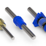
As a lead screw nut wears, its threads degrade and become thinner. Manufacturers consider the life of the nut to be the point when the threads have lost ½ of the tooth thickness (¼ of the screw pitch). At this point, the nut will no longer have the material strength to support is full load rating.

Image credit: Nook Industries
Another consequence of decreasing tooth thickness is that the displacement, or backlash, between the screw and nut increases. A follower nut, or wear indicator nut, makes it easy to monitor this increase in backlash and determine the level of wear on the nut.

Image credit: Nook Industries
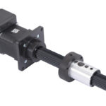
The follower nut and main nut are typically both made of bronze, although the follower nut can be made of steel. The follower nut is pinned to the main nut, so it “follows along,” but it does not support the load.
As the main nut wears and its thread becomes thinner, it begins to “close the gap” between it and the follower nut. By measuring this gap — either with feeler gauges or with a proximity sensor — an operator can determine how much wear has occurred. When the gap indicates that ½ (or more) of the tooth thickness is gone, the main nut can be replaced to avoid failure.
Alternatively, if the follower nut is made of steel, when the main nut begins to fail, the follower nut takes up some of the load, resulting in steel-to-steel sliding between it and the screw, which causes noise that serves as an audible indicator of wear.


Leave a Reply
You must be logged in to post a comment.