
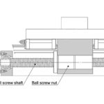
Ball and lead screws are specified by the diameter of the screw shaft and the lead (or, in some cases, pitch) of the screw thread. The lead, which specifies how far the nut travels for each revolution of the screw, is created by the thread, or helix, that wraps around the screw shaft.
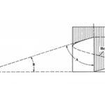
If the helix is “unwrapped” from the screw, it can be used, together with the screw’s circumference and lead, to form a right triangle. The helix serves as the hypotenuse of the triangle, with the circumference and lead making up the other two sides.
In this triangle, the angle made up by the screw circumference and the helix is known as the lead angle (B). The angle formed by the lead and the helix is known as the helix angle (A). The lead angle and helix angles are complementary (their sum must equal 90 degrees), so if the lead angle gets larger, the helix angle will get smaller.
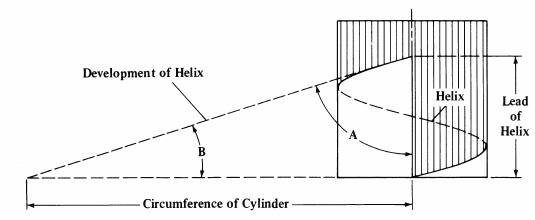
Image credit: tools-n-gizmos.com
Note that some reference materials refer to the angle (B), between the screw circumference and the helix, as the helix angle. When the term “helix angle” is used, be sure to look for a definition or diagram to confirm which angle is being referenced.
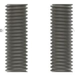
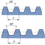
A high helix screw is generally recognized as one whose lead (P) is equal to or larger than the screw diameter (d0).
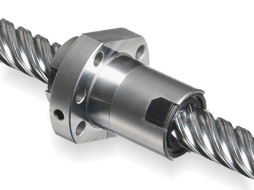
Image credit: Eichenberger Gewinde
Examples of high helix screws are sizes 20 x 20, 6 x 25, and 40 x 80, and some high helix designs have leads that are up to six times the diameter of the screw. And the larger the lead, the faster the linear travel speed. So high helix screws maximize linear travel speed while keeping the diameter, mass, and inertia of the screw small. And by keeping the rotational speed low, audible noise and vibrations are reduced.
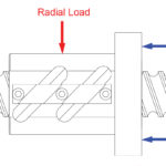
Because the lead of a high helix screw is large — that is, the helix that wraps around the screw is “stretched out” — there are fewer effective turns of balls (in the case of a ball screw) or less screw-nut contact (in the case of a lead screw) to support the load. To counter this situation, some manufacturers add additional ball tracks, or turns, to the screw shaft — a design typically referred to as a multi-start screw. For ball screws, adding turns, or tracks, increases the number of balls available to carry the load. For lead screws, adding turns increases the amount of contact area available to carry the load — but it also increases friction and heat, which can affect the PV value of the screw.
The opposite of a high helix, or high lead, screw is a fine pitch, or fine lead, screw. Fine pitch screws are generally defined as those with a lead that’s less than one-half the screw diameter, such as a 16 x 5 or a 12 x 2 size. Fine pitch screws are typically used when very small moves are required.

Leave a Reply
You must be logged in to post a comment.