• Skip to primary navigation
  • Skip to main content
  • Skip to primary sidebar
  • Skip to footer

Linear Motion Tips

Covering Linear Motion Systems, Components and Linear Motion Resources

  • New
    • Editor’s blog
    • Industry news
    • Motion Casebook
    • Video
  • Applications
  • Slides + guides
    • Ball + roller guides
    • Track roller (cam + wheel) guides
    • Crossed-roller slides
    • Linear bearings
    • Plastic + composite guides
  • Drives
    • Ball + lead + roller screws
    • Belt + chain drives for linear
    • Rack + pinion sets
  • Actuators
    • Ball + leadscrew driven
    • Belt + chain driven
    • Linear motors
    • Mini + piezo + voice coil
    • Rack + pinion driven
    • Rigid-chain actuators
  • Encoders + sensors (linear) + I/O
  • Stages + gantries
  • Suppliers

What is a split bridge system and how does it differ from a gantry?

December 23, 2021 By Danielle Collins Leave a Comment

Multi-axis linear systems come in a variety of designs, with Cartesian, gantry, and XY tables being some of the most common types. While these designs simplify construction and can provide space savings, they also introduce “stacking” errors — the compounding of errors from each axis, which manifests at the work piece or tool point. Mounting axes to one another also creates cantilevered loads and Abbé errors — angular errors that are amplified as the point of interest (work piece or tool point) moves farther from the source of the error. But one multi-axis configuration — the split bridge system — provides a solution for high-precision tasks that require multiple axes of motion while minimizing stacking errors.

split bridge system
In a split bridge system, one axis is not connected to the others, but works in conjunction with them.
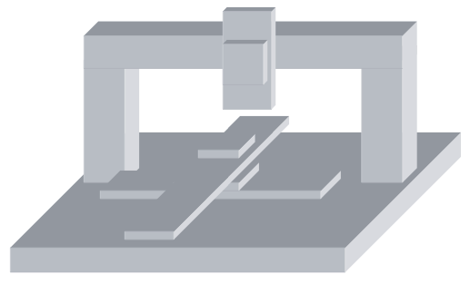
Image credit: Parker Motion

Split bridge systems provide two, three, or more axes of motion using a cross, or bridge, axis that spans the base and supports at least one of the axes. While this setup is similar to a traditional gantry, there are some notable differences. To start, a traditional gantry system uses two X, or base, axes with a Y axis that spans across them and — in most applications — a Z (vertical) axis mounted to the Y axis. The gantry design provides very long travel lengths with good load capacity and high rigidity, since roll moments on the X axis are eliminated and yaw moments can be minimized. But if the parallel X axes aren’t synchronized, racking, or skewing of the axes can occur, which will produce errors in the Y and Z axis positions.

racking
Gantry systems use two, parallel X axes with a Y axis that spans them and – in many cases – a Z axis mounted to the Y axis. This design allows for long travel lengths, but often introduces errors in the Y and Z axis motions.
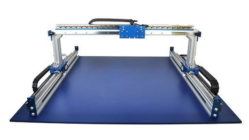
Image credit: H2W Technologies

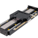
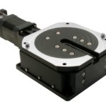
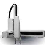
A split bridge system avoids these issues by using a static member, or fixed bridge, to span the base axis or axes. The base axes — whether a single axis, an XY table, or a two-axis planar gantry — are mounted to a machined surface (typically steel or granite, although machined aluminum is sometimes used) for flatness and rigidity. The Z, or vertical, axis is mounted to the bridge, independent of the base axes. And in some cases both Y and Z axes are mounted to the bridge, making them both independent of the X axis. The axes mounted to the bridge are typically high-precision stages, like the base axes, although more traditional linear systems can also be used, depending on the application requirements.
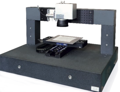
split bridge system
This split bridge system for laser processing includes an XY stage, which moves the sample for scanning, and an independent Z axis, which moves the laser scanner.
Image credit: PI

One of the primary reasons for using a split bridge system is so a part or sample can be moved into a very precise position with the base axes, and then a process such as scanning, probing, or drilling can be done by the axis (or axes) mounted on the bridge.

split bridge system
This split bridge system uses four Z axis stages on the bridge for higher throughput.
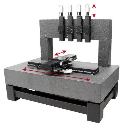
Image credit: Aerotech

You may also like:

  • linear stage
    What makes a linear stage different from other types of…

  • What’s the difference between a vertical lift stage and a…
  • Cartesian robots
    Three important design considerations for Cartesian robots
  • roll pitch yaw
    Motion basics: How to define roll, pitch, and yaw for…
  • planar stages
    What are planar stages and gantries?

Filed Under: FAQs + basics, Featured, Stages + gantries

Reader Interactions

Leave a Reply

You must be logged in to post a comment.

Primary Sidebar

DESIGN GUIDE LIBRARY

“motion
Subscribe Today

RSS Featured White Papers

  • Evaluating actuators for washdown in food & beverage applications
  • Identifying Best-Value Linear Motion Technologies
  • Introduction to accuracy and repeatability in linear motion systems

RSS Motion Control Tips

  • Schneider Electric launches Universal Automation Discovery Packs to foster industrial innovation
  • Encoders from SIKO support Industrial Ethernet
  • Draw-wire encoders from SIKO measure position, speed and inclination
  • Incremental encoders configurable via NFC (near-field communication)
  • Low-cost motion control offered with CLICK PLUS PLCs from AutomationDirect

Footer

Linear Motion Tips

Design World Network

Design World Online
The Robot Report
Coupling Tips
Motion Control Tips
Bearing Tips
Fastener Engineering

Linear Motion Tips

Subscribe to our newsletter
Advertise with us
Contact us
About us

Follow us on TwitterAdd us on FacebookAdd us on LinkedInAdd us on YouTubeAdd us on Instagram

Copyright © 2022 · WTWH Media LLC and its licensors. All rights reserved.
The material on this site may not be reproduced, distributed, transmitted, cached or otherwise used, except with the prior written permission of WTWH Media.

Privacy Policy