
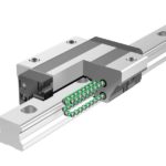
Several types of non-recirculating linear bearings use a cage to contain the rolling elements, maintain consistent spacing between them, and ensure even load distribution. But in each of these non-recirculating designs, the cage “floats” between the two moving components, meaning that it’s not constrained and can gradually move away from its intended, centered position. This movement of the cage is referred to as cage creep.
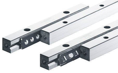
Image credit: Schneeberger
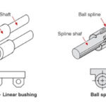
Linear bearing types that use cages include crossed roller slides, telescoping slides, needle roller bearing linear guides, and stroke ball splines.
Although a cage isn’t necessary for the proper operation of a crossed roller slide, many designs use cages to prevent contact between the rolling elements, which in turn, reduces noise and friction.
In telescoping slides, the cage not only contains the rolling elements and ensures even load distribution, it also determines the slide’s load capacity for applications with shorter strokes — particularly in partial extension designs. (For longer-stroke applications — typically achieved with full extension or over-extension designs — the rigidity of the intermediate element determines the slide’s load capacity.)
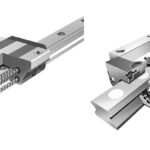
Cages are also used in both recirculating and non-recirculating types of needle roller bearing linear guides, to contain the rollers and ensure their proper movement during the stroke.
Unlike their regular ball spline counterparts, the balls in a stroke ball spline don’t recirculate, and so require a cage (also referred to as a ball retainer) to hold the balls.
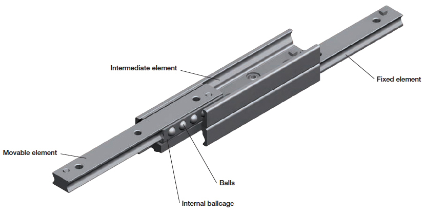
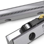
Image credit: Rollon
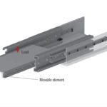
In ideal applications, the cage will remain in its intended, centered position. But if the full stroke of the bearing isn’t used, or if there are shock or vibration loads, the cage can move, or creep, to one end of the bearing assembly. Vertical applications can also induce cage creep, simply due to the force of gravity.
When the cage becomes misaligned from its center position, it can shorten the stroke of the bearing, and if end stops are provided at the ends of the rails, the cage can bump into the end stop when a full stroke is attempted. Although this forces the cage back to its centered position, it causes both the cage and the balls (or rollers) to slide, rather than roll, which increases friction and heat. The force of the cage hitting an end stop can also damage the cage or one of the guide elements.
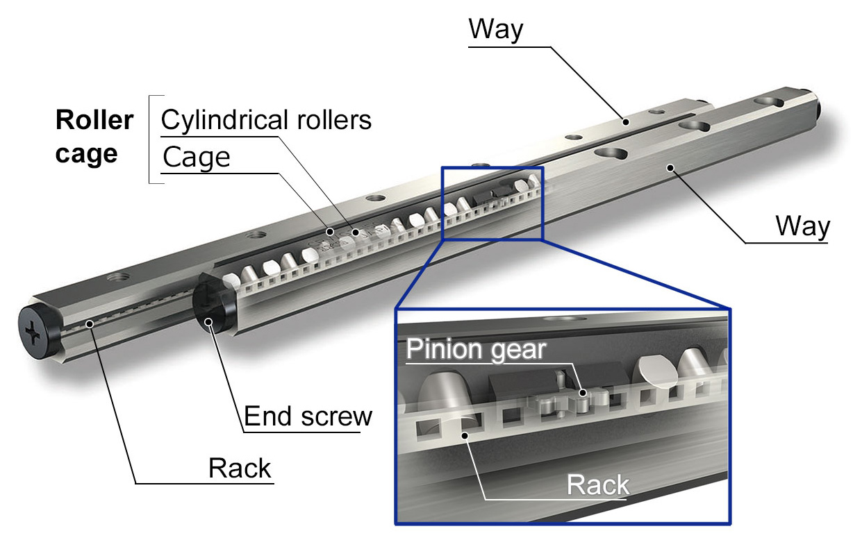
Image credit: IKO Nippon Thompson
Manufacturers have developed several methods to combat cage creep. One popular method is to use a rack and pinion type assembly, with the pinion gear integrated into the cage and the rack integrated into one of the guide rails. Another method is to use a studded center roller that meshes with indentations machined into one of the rails.
Image credit: Nippon Bearing
A few types of linear guides don’t require or don’t use anti-creep mechanisms. For example, recirculating linear bearings that use cages — such as the needle roller types described above — don’t experience cage creep, since the cage is an endless component that runs completely around the recirculation path. And although stroke ball splines do experience cage creep, their design and compact size precludes the use of anti-creep mechanisms, so it’s important to incorporate occasional full-length strokes to re-center the cage – especially if the application involves high travel speeds or vertical installations.

Leave a Reply
You must be logged in to post a comment.