
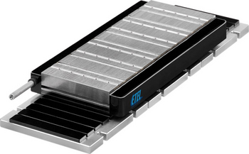
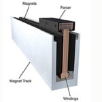
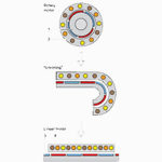
Linear motors are generally classified by the construction of the motor’s primary part: ironless or iron core. In an ironless linear motor, the windings of the primary are embedded in an epoxy resin, whereas the windings of an iron core linear motor are mounted in an iron lamination stack. The lamination contains teeth, or protrusions, that focus the electromagnetic flux towards the magnets of the secondary part. Windings are mounted in the slots between the teeth.
This design provides a strong magnetic attraction between the primary and the secondary and allows iron core linear motors to produce very high forces, but the lamination slots cause a phenomenon known as cogging.
As the slotted primary part travels across the magnets of the secondary, it has “preferred” positions relative to the magnets. In order to keep the motor in motion when the primary reaches these preferred positions, more force is required. This force variation (and resulting velocity ripple) is known as cogging. Cogging reduces the smoothness of motion of iron core motors and typically makes them less suitable than ironless designs for applications that require smooth, constant force or velocity.
Hardware and software solutions to cogging
There are several methods that can be used to reduce cogging. One of the most common is to skew the positions of the magnets. This lessens the change in magnitude of the attractive forces as the primary moves across the magnets of the secondary. Skewing the slots in the laminations produces similar results, as does changing the shape of the magnets. But all three of these methods weaken the cogging forces by misaligning the laminations and magnets, which reduces the motor’s force production and efficiency.
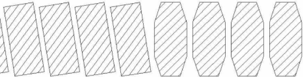
Image credit: Parker Hannifin
Another approach to the problem of cogging in iron core motors relies on destructive interference. This method uses a winding method referred to as fractional winding, in which there are more lamination teeth in the primary than there are magnets in the secondary. This design cancels out the cogging forces caused by the “inner” teeth of the lamination. The forces from the outermost teeth are then eliminated by a special assembly that effectively adds a triangular component to each end of the lamination (making its shape a parallelogram rather than a rectangle). This “anti-cog assembly” produces a cogging force that is equal but opposite to that of the lamination and cancels out the cogging forces that remain due to the outermost teeth of the lamination.
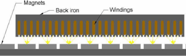
Image credit: Parker Hannifin
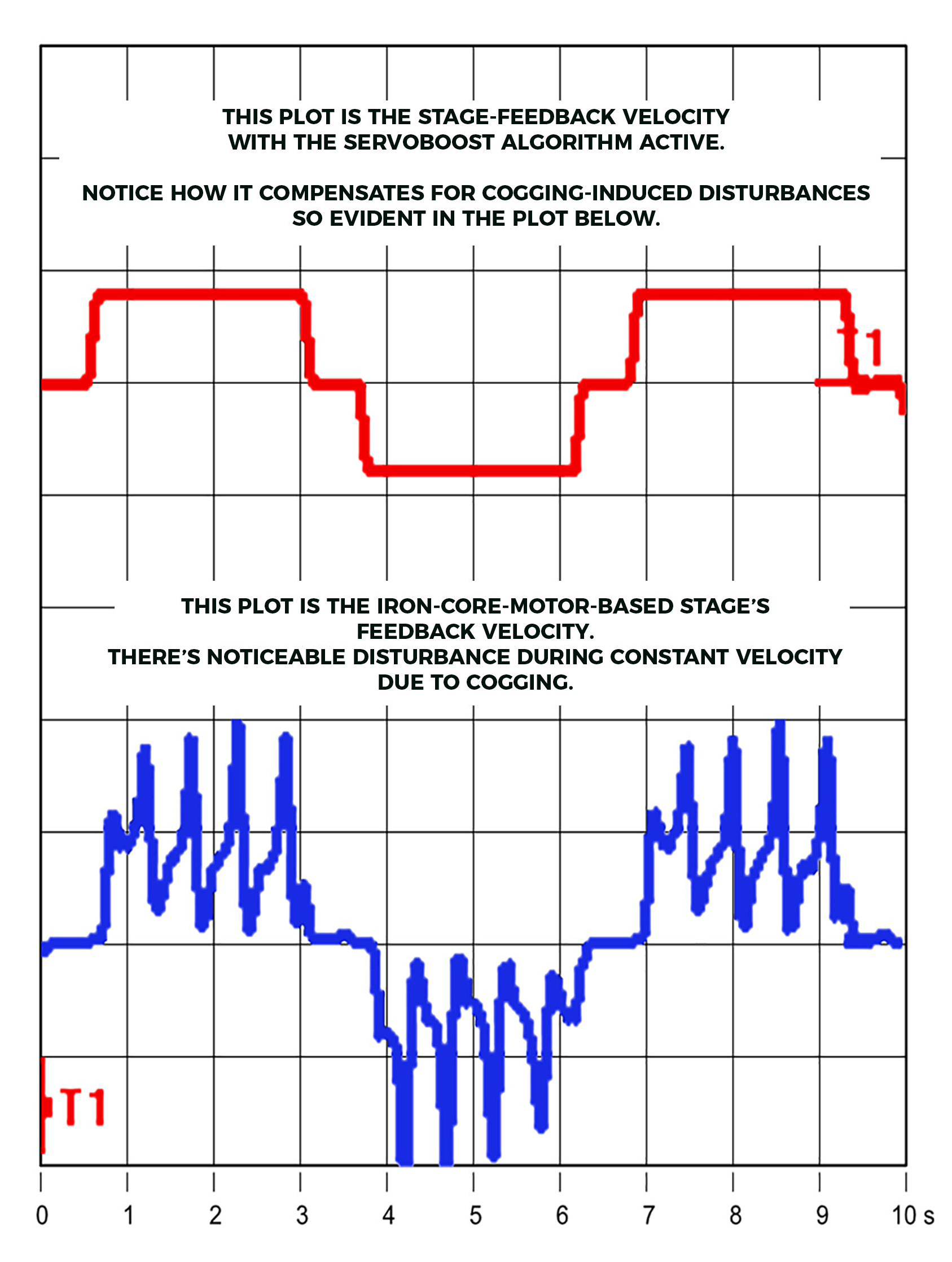
In addition to these mechanical solutions, many servo drives and controllers include algorithms that can compensate for cogging forces. This is done by adjusting current to the motor in order to minimize variations in force and velocity. Anti-cogging algorithms can help iron core motors achieve motion that rivals ironless versions in smoothness and consistency.

Leave a Reply
You must be logged in to post a comment.