• Skip to primary navigation
  • Skip to main content
  • Skip to primary sidebar
  • Skip to footer
  • Advertise
  • Subscribe

Linear Motion Tips

Covering Linear Motion Systems, Components and Linear Motion Resources

  • News
    • Editor’s blog
    • Industry news
    • Motion Casebook
  • Applications
  • Slides + guides
    • Ball + roller guides
    • Track roller (cam + wheel) guides
    • Crossed-roller slides
    • Linear bearings
    • Plastic + composite guides
  • Drives
    • Ball + lead + roller screws
    • Belt + chain drives for linear
    • Rack + pinion sets
  • Actuators
    • Ball + leadscrew driven
    • Belt + chain driven
    • Linear motors
    • Mini + piezo + voice coil
    • Rack + pinion driven
    • Rigid-chain actuators
  • Encoders + sensors (linear) + I/O
  • Stages + gantries
  • Resources
    • Suppliers
    • Video

What is an inverted roller screw and how does it work?

★ By Danielle Collins Leave a Comment

Roller screws are often thought of as the standard planetary design, but several variations exist, including differential, recirculating, and inverted versions. Each design offers unique benefits in performance capabilities — load capacity, torque, and positioning — but the inverted roller screw’s primary strength is its ability to be easily integrated into actuators and other subassemblies.

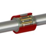
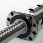
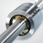
Recall that a standard roller screw (also referred to as a planetary roller screw) uses threaded rollers, with the ends of the rollers being toothed to mesh with geared rings at each end of the nut. For an inverted roller screw, the functions of the screw and the nut are interchanged, or inverted. The nut is essentially a tube with a threaded inner diameter, and rather than its length being just sufficient to accommodate the rollers and mating geared rings, the nut is made the length of the stroke. And the screw shaft — rather than being threaded along its entire length — is threaded for a length just equal to that of the rollers.

inverted roller screw
With an inverted roller screw, the nut length determines the stroke and the screw is only threaded for a portion equal to the roller length.
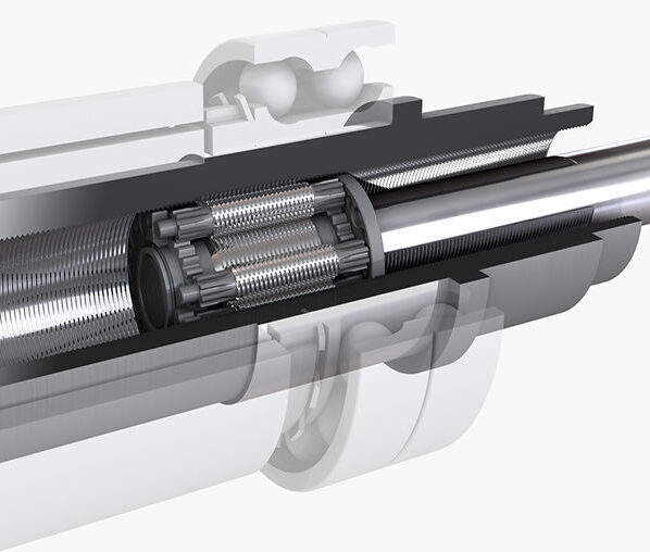
Image credit: Ewellix

So when the screw shaft is turned, instead of the nut and rollers translating along the length of the screw, the rollers remain axially stationary on the screw (that is, the rollers and nut don’t travel along the screw length). Instead, turning the screw shaft causes the rollers — and the screw — to translate along the length of the nut. Alternatively, it is possible with an inverted roller screw to drive the nut and hold the screw (and rollers) axially stationary.

This animation from Rollvis shows the inner workings of an inverted roller screw.

With the geared rings that normally reside at the end of the nut now positioned at the ends of the threaded section of the screw, the nut diameter can be made slightly smaller than that of a similar sized planetary roller screw. Although machining the threads inside the relatively long nut body can be difficult, inverted roller screws can have fewer starts than standard planetary roller screws, meaning they can use a larger thread and, in turn, provide higher load capacities than standard designs.

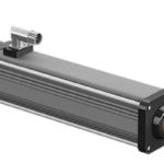
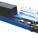
Inverted roller screws are ideal for thrust rod style actuators, in which a push rod extends and retracts from the actuator housing. And because a significant portion of the screw shaft is not threaded (only the section where the rollers reside is threaded), the shaft can be customized to suit the actuator’s design and application requirements. The inverted design also makes it relatively easy for actuator manufacturers to attach magnets to the roller screw nut and implement it as the rotor for an integrated motor-screw assembly.

While manufactures often tout the compactness of inverted roller screws as their primary benefit, for thrust rod actuator applications, the ability to customize the unthreaded portion of the screw shaft gives them a significant edge over other screw designs.
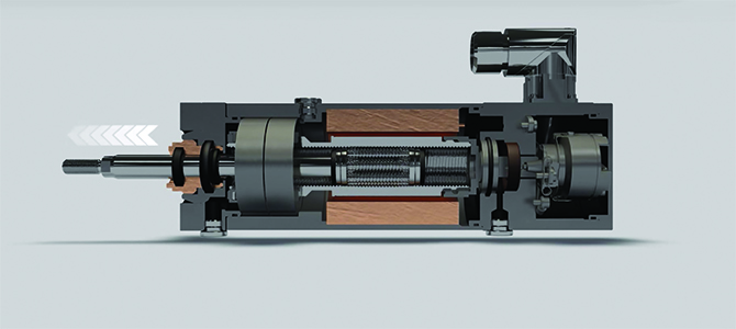
Image credit: Diakont

You Might Also Like

Filed Under: Ball + lead + roller screws, Ball + leadscrew driven, FAQs + basics, Featured, Linear actuators (all)

Reader Interactions

Leave a Reply

You must be logged in to post a comment.

Primary Sidebar

LEARNING CENTER

Design World Learning Center
“lmt
EXPAND YOUR KNOWLEDGE AND STAY CONNECTED
Get the latest info on technologies, tools and strategies for Design Engineering Professionals.
“linear

RSS Motion Control Tips

  • PI unveils motion solutions at LASER World of PHOTONICS
  • Rollon marks 50 years with new facility opening in Michigan
  • Controller/drive features FOC and sensorless control
  • Allient expands its Allied Motion SA Axial Flux Motor series
  • PICMA Plus piezo actuators offer extended displacement range

RSS Featured White Papers

  • Robotic Automation is Indispensable for the Logistics Industry’s Continued Growth and Success
  • Reliable Linear Motion For Packaging Machines
  • Technical Brief – “Understanding the Extensive Benefits of Total Linear Positioning Systems.”

Footer

Linear Motion Tips

Design World Network

Design World Online
The Robot Report
Coupling Tips
Motion Control Tips
Bearing Tips
Fastener Engineering
Wire and Cable Tips

Linear Motion Tips

Subscribe to our newsletter
Advertise with us
Contact us
About us

Copyright © 2025 · WTWH Media LLC and its licensors. All rights reserved.
The material on this site may not be reproduced, distributed, transmitted, cached or otherwise used, except with the prior written permission of WTWH Media.

Privacy Policy