
In previous articles, we’ve covered a variety of technologies for measuring linear position: magnetic and optical encoders, magnetostrictive sensors, and even measuring systems integrated into linear guide systems. Another technology for measuring absolute linear position is the linear variable differential transformer (LVDT).

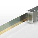
A linear variable differential transformer is an induction-based measuring system that consists of a transformer and a core. The transformer is made up of three coils that are wound on a hollow form, which is typically made of glass-reinforced polymer. The primary coil is located between the two secondary coils, and the secondary coils are wound in series but in opposite directions — a configuration referred to as “series-opposed winding.”
The core, which is made of magnetically permeable material, moves freely inside the hollow bore of the transformer. A non-ferromagnetic push rod, or shaft, is attached to the core and also attaches to the moving part of the object being measured.

Image credit: Honeywell International
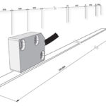
When voltage is applied to the primary coil, magnetic flux is produced. This flux is coupled to the secondary coils by the core, causing a voltage to be induced in each of the secondary coils.
With the core located at the center of the transformer (equidistant between the two secondary coils), the series-opposed windings produce induced voltages (E1 and E2) that are equal in amplitude but out of phase by 180 degrees, and therefore, cancel each other out. In other words, the output voltage is zero. This is often referred to as the null point.
When the core moves away from the center of the transformer, closer to the S1 coil, for example, the S1 coil becomes more strongly coupled to the core, and the induced voltage in the S1 coil is higher than the induced voltage in the opposite (S2) secondary coil. The distance of movement is determined by the differential voltage output of the two secondary coils (E1 – E2).
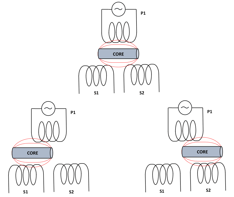
Image credit: NewTek Sensor Solutions
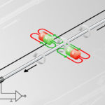
The direction of motion is determined by examining whether the induced voltage of the secondary coil is in phase or out of phase with the primary voltage. If the core moves toward the first secondary coil (S1), the induced voltage in the S1 coil will be in phase with the primary voltage, indicating that the core has moved in the direction of S1.
Conversely, if the core moves toward the opposite secondary coil (S2), the induced voltage in the S2 coil will be out of phase with the primary voltage, indicating that the core has moved in the direction of S2.
The output from a linear variable differential transformer is a direct, linear function of the input for its specified measuring range. However, it is possible to use an LVDT beyond its specified measuring range, with a predefined table or polynomial function that provides compensation for the nonlinearity. And because it relies on the coupling of magnetic flux, an LVDT has nearly infinite resolution, limited only by the signal conditioning electronics. Similarly, repeatability is extremely high — typically less than 0.1 percent of the measurement range. (Typical measurement ranges are from ± 0.25 mm to ± 750 mm.)
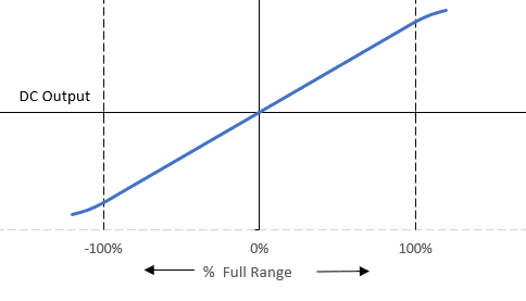
Image credit: NewTek Sensor Solutions
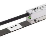
The electronics required for an LVDT, referred to as a signal conditioner, includes an oscillator to generate the drive signal, a demodulator, an amplifier, and a low-pass filter that converts the AC output voltage to a DC signal. Traditional designs keep the electronics external to the LVDT. But housing the signal conditioning electronics within the LVDT allows the primary coil to be supplied with DC voltage, which is beneficial in batter-powered applications. This design is often referred to as a DC LVDT. Although housing the electronics internally reduces complexity, it also reduces the device’s resistance to shocks, vibrations, and temperature extremes.

Image credit: TE Connectivity
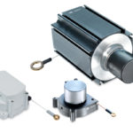
Key benefits of linear variable differential transformers are their absolute output and almost infinite resolution, along with extremely high repeatability. LVDTs are extremely rugged — with no physical contact between the core and the transformer bore, there is no friction and, therefore, no wear to reduce the life of the system. And in most LVDT designs, the transformer is encapsulated in epoxy, so the internal components are protected against contamination and moisture. The housing can also be made from a variety of materials, including stainless steel, nickel alloys, or titanium to meet specific environmental requirements.

Leave a Reply
You must be logged in to post a comment.