
Gantries differ from other types of multi-axis systems (such as Cartesian robots and XY tables) by using two base (X) axes in parallel, with a perpendicular (Y) axis connecting them. While this dual X-axis arrangement provides a wide, stable footprint and allows gantry systems to deliver high load capacity, long travel lengths, and good rigidity, it can also lead to a phenomenon commonly referred to as racking.
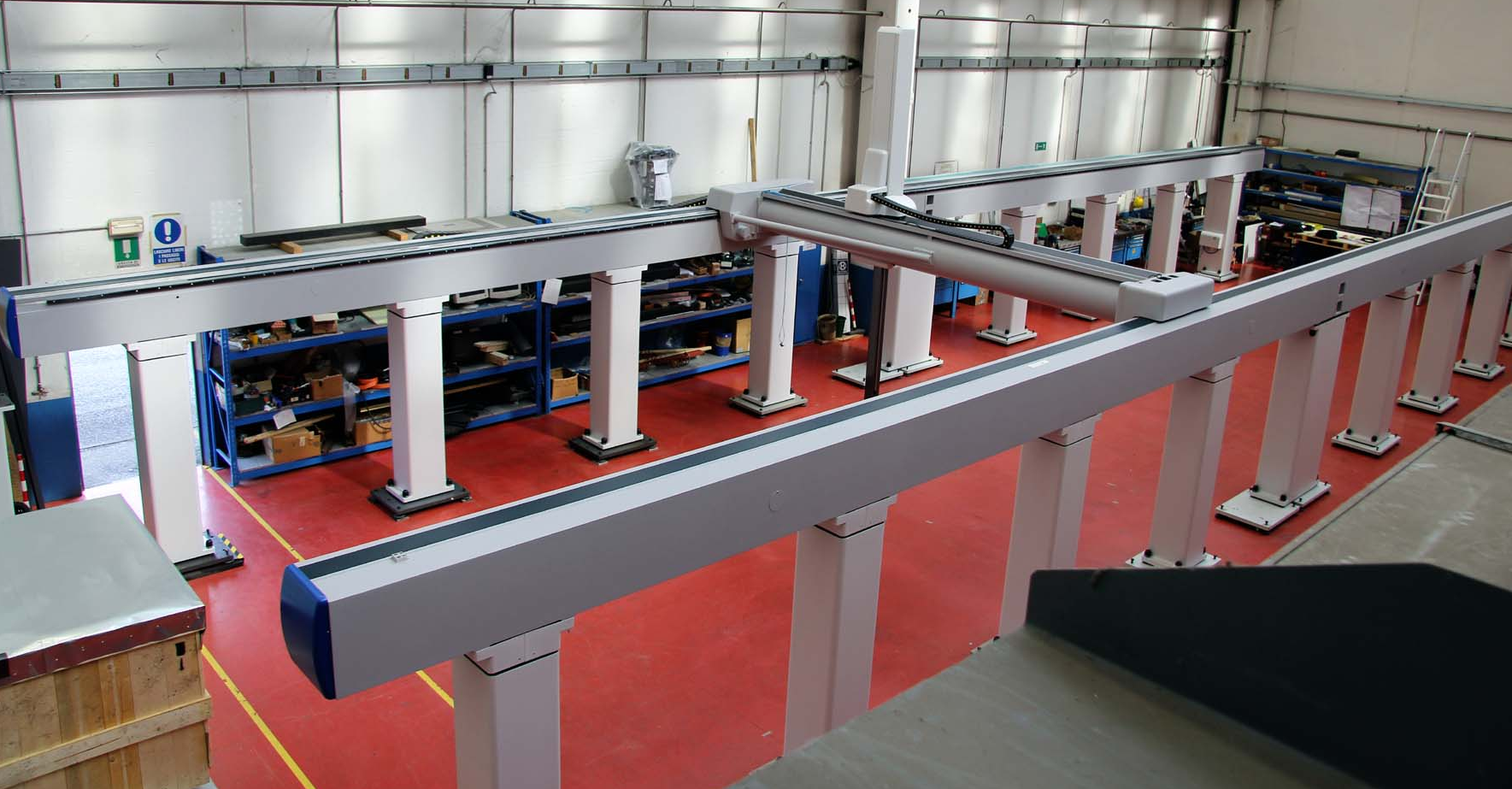
Image credit: Coord3
Any time two linear axes are mounted and connected in parallel, there is a risk that the axes don’t travel in perfect synchronization. In other words, during movement, one of the X axes can “lag behind” the other, and the leading axis will attempt to pull its lagging partner along. When this happens, the connecting (Y) axis can become skewed — no longer perpendicular to the two X axes. The condition where the X and Y axes lose orthogonality is referred to as racking, and it can result in binding as the system moves in the X direction as well as potentially damaging forces on both the X and Y axes.
Racking in gantry systems can be caused by a variety of design and assembly factors, but one of the most influential factors is the method of driving the X axes. With two X axes in parallel, designers have the choice of driving each X axis independently, or driving one axis and treating the other as a “slave,” or follower, axis.
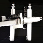
In low-speed applications with a relatively small distance between the two X axes (short Y axis stroke), it can be acceptable to drive only one X axis and allow the second X axis to be a follower, with no driving mechanism. In this design, a key concern is the rigidity of the connection between the axes — in other words, the rigidity of the Y axis.
Since the driven axis is effectively “pulling along” the non-driven axis, if the connection between them experiences bending, twisting, or other non-rigid behavior, any difference in friction or load between the two X axes can immediately lead to racking and binding. And the longer the Y axis, the less rigid it will be. This is why the “driven-follower” arrangement is generally recommended for applications where the distance between X axes is less than one meter.
Image credit: Animatics
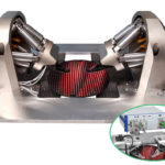
The more sophisticated drive solution is to use a separate motor on each axis, with the motors synchronized in a master-slave arrangement via the controller. In this arrangement, however, the travel errors of the mechanical drives need to be perfectly (or near-perfectly) matched — otherwise, racking and binding can be caused by slight deviations in the distance that each axis travels per motor revolution.
For high-speed, precision gantry applications, the drive mechanisms of choice are typically ball screws and rack and pinion drives. Both of these technologies can be selectively matched to provide similar linear error on each axis, avoiding some of the error stack-up that can occur in unmatched drive assemblies. Because belt and chain drives have pitch errors that are difficult to match and compensate, these are not generally recommended for gantry systems when the X axes are independently driven. On the other hand, linear motors are an excellent choice for parallel axes in gantry systems, since they have no mechanical error and can provide long travel lengths and high speeds.
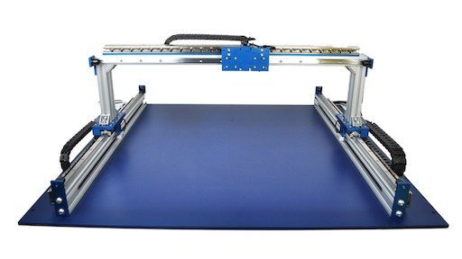
Image credit: H2W Technologies
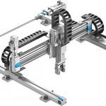
Another solution — somewhat of a compromise between the two options described above — is to use one motor to drive both X axes. This can be done by connecting the output of the motor-driven axis to the input of the second axis via a distance coupling (also referred to as a connecting shaft). This configuration eliminates the second motor (and the accompanying synchronization that would be required).
However, the torsional rigidity of the distance coupling is important. If the torque being transferred between the axes causes the coupling to experience “wind-up,” racking and binding can still occur. This configuration is often a good option when the distance between the X axes is between one and three meters, with moderate load and speed requirements.
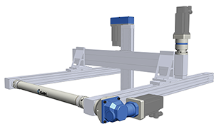
Image credit: GAM


Leave a Reply
You must be logged in to post a comment.