
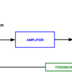
Unlike stepper motors, which rely on even pulses of current to turn the motor in discreet steps, servo motors operate with continuous current to reach a specified position, velocity, or torque. The precise amount of current to be delivered to the motor is determined by the servo controller, based on information supplied by an encoder regarding the system’s actual condition (position, speed, or torque). The controller sends these current commands to the servo drive (also referred to as an amplifier), which provides the motor with the precise current needed to adjust for any differences between the commanded value (position, speed, or torque) and the actual value.
When we talk about “accuracy” in a linear system, we typically refer to the positioning accuracy and repeatability of the mechanical drive (screw or belt, for example). But regardless of how accurate the mechanical system is, if the servo motor doesn’t receive the proper amount of current, it can’t produce the necessary torque (either too much or too little) to drive the mechanical system to the intended position.
Servo tuning via PID loops
Tuning a servo system involves adjusting the gains in the motion controller to minimize the servo system’s response time, settling time, and overshoot. The goal of servo tuning is to minimize (but not necessarily eliminate) the error between the commanded position (or speed or torque) and the actual value achieved.
The most common type of control loop, or algorithm, used for servo tuning is a PID loop, where “P” refers to proportional gain, “I” refers to integral gain, and “D” refers to derivative gain. A gain is essentially a ratio of output to input, and in a servo control loop, the gains determine how — and to what extent — the controller tries to correct the errors detected by the feedback device.
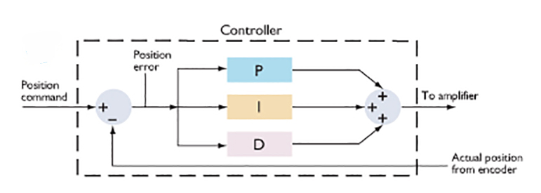
Image credit: Performance Motion Devices, Inc.
The amount of proportional gain in the control loop determines how much restoring force is applied to overcome the error between the commanded value and the actual value. The proportional gain is multiplied by the error and generates the contribution to the output for the next time period. The term “proportional” is used because the amount of restoring force is directly proportional to the amount of error at any instant in time.
Integral gain is used to “push” the system to zero error at the end of the move. The integral gain value increases with time — hence, the term “integral.” However, because the integral gain increases at the end of the move, it can cause the system to overshoot or oscillate. And if the integral gain is too low, the system will have a slow response time. Integral gain is primarily used when the system is subjected to static torque loads.
Derivative gain is proportional to the rate of change (the derivative) of the error. It’s often used in conjunction with proportional gain to reduce overshoot and provide damping. But a derivative gain that is too high can reduce system response time and cause oscillations.
Feed-forward gains for highly dynamic applications
The PID gains described above are reactive corrections to the system’s behavior over time. For highly dynamic applications, or for better responsiveness, another type of gain — referred to as feed-forward gain — works outside the feedback loop and provides a proactive approach to error correction by predicting the commands needed to achieve zero error (rather than waiting for the error to develop). Feed-forward gains are classified as either velocity feed-forward or acceleration feed-forward.
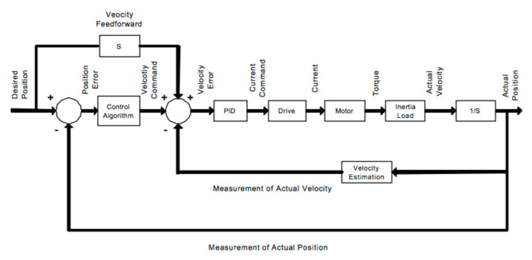
Image credit: Integrated Industrial Technologies, Inc.
Velocity feed-forward works during the constant velocity portion of the move profile. It minimizes following error and improves response time by multiplying the derivative of the position command (i.e. the velocity) by the velocity feed-forward gain value.
Acceleration feed-forward works during the acceleration and deceleration portions of the move and can eliminate overshoot caused by velocity feed-forward. Acceleration feed-forward multiplies the second derivative of the position command (i.e. the acceleration) by the acceleration feed-forward gain value.

Leave a Reply
You must be logged in to post a comment.