
Motors produce torque and rotation through the interaction of magnetic fields in the rotor and the stator. In an ideal motor — with mechanical components that are perfectly machined and assembled and electrical fields that build and decay instantaneously — torque output would be perfectly smooth, with no variations. But in the real world, there are a variety of factors that cause torque output to be inconsistent — even if only by a small amount. This periodic fluctuation in output torque of an energized motor is referred to as torque ripple.
Mathematically, torque ripple is defined as the difference between the maximum and minimum torque produced over one mechanical revolution of the motor, divided by the average torque produced over one revolution, expressed as a percentage.

In linear motion applications, the main effect of torque ripple is that it causes motion to be inconsistent. And because motor torque is required to accelerate an axis to a specified velocity, torque ripple can cause velocity ripple, or “jerky” motion. In applications such as machining and dispensing, this inconsistent motion can have a significant effect on the process or end product — such as visible variations in machining patterns or in the thickness of dispensed adhesives. In other applications, such as pick and place, the torque ripple and smoothness of motion may not be a critical performance issue. That is, unless the roughness is severe enough to cause vibrations or audible noise — especially if the vibrations excite resonances in other parts of the system.
The amount of torque ripple a motor produces depends on two main factors: the motor’s construction and its method of control.
Motor construction and cogging torque
Motors that use permanent magnets in their rotors — such as brushless DC motors, stepper motors, and synchronous AC motors — experience a phenomenon known as cogging, or cogging torque. Cogging torque (often referred to as detent torque in the context of stepper motors) is caused by the attraction of the rotor and the stator teeth at certain rotor positions.

Image credit: Kollmorgen
Although typically associated with the “notches” that can be felt when an unpowered motor is turned by hand, cogging torque is also present when the motor is powered, in which case it contributes to the motor’s torque ripple, especially during slow speed operation.
There are ways to mitigate cogging torque and the uneven torque production that results from it — by optimizing the number of magnetic poles and slots, and by skewing or shaping the magnets and slots to create overlap from one detent position to the next. And a newer type of brushless DC motor — the slotless, or coreless, design — does away with cogging torque (although not torque ripple) by using a wound stator core, so there are no teeth in the stator to create periodic attractive and repulsive forces with the rotor magnets.

Image credit: Lin Engineering
Cogging torque can also occur in AC induction motors, in which the rotor’s magnetic field is induced by the stator’s field, rather than being produced by magnets. However, to avoid cogging, AC induction motors are constructed so that the ratio of rotor slots to stator slots is a non-integer multiple.
Motor commutation and torque ripple
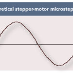
Permanent magnet brushless DC (BLDC) and synchronous AC motors are often differentiated by the way their stators are wound and the commutation method they use. Permanent magnet synchronous AC motors have sinusoidally wound stators and use sinusoidal commutation. This means that current to the motor is continuously controlled, so torque output remains very constant with low torque ripple.
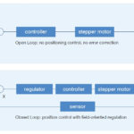
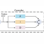
For motion control applications, permanent magnet AC (PMAC) motors may use a more advanced control method known as field oriented control (FOC). With field oriented control, the current in each winding is measured and controlled independently, so torque ripple is reduced even further. With this method, the bandwidth of the current control loop and the resolution of the feedback device also affect the quality of torque production and amount of torque ripple. And advanced servo drive algorithms can further reduce or even eliminate torque ripple for extremely sensitive applications.
In contrast to PMAC motors, brushless DC motors have trapezoidally wound stators and typically use trapezoidal commutation. With trapezoidal commutation, three Hall sensors provide information on the position of the rotor every 60 electrical degrees. This means that current is applied to the windings in a square waveform, with six “steps” per electrical cycle of the motor. But current in the windings can’t rise (or fall) instantaneously due to the windings’ inductance, so torque variations occur at each step, or every 60 electrical degrees.
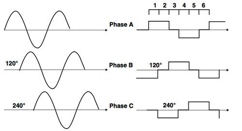
Image credit: STMicroelectronics
Because the frequency of the torque ripple is proportional to the motor’s rotational speed, at higher speeds, the motor and load inertia can serve to smooth out the effects of this inconsistent torque. Mechanical methods to reduce torque ripple in BLDC motors include increasing the number of windings in the stator or the number of poles in the rotor. And BLDC motors — like PMAC motors — can use sinusoidal control or even field-oriented control to improve the smoothness of torque production, although these methods increase system cost and complexity.

Leave a Reply
You must be logged in to post a comment.