
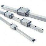
High-speed motion is a requirement for applications where throughput is a critical factor, such as packaging and electronic assembly. These systems typically use linear motors or steel reinforced belt drives in conjunction with recirculating linear bearing guides for good stiffness and high load capacity. But the speeds demanded by these applications can pose a challenge for recirculating linear bearings, which are typically rated for maximum speeds of 3 m/s (9.8 ft/s).
Depending on the type of linear guide and the manufacturer, a load factor of between 2 and 4 may be recommended when the maximum speed exceeds 2 m/s (6.6 ft/s). When calculating bearing life, the bearing’s dynamic load capacity is divided by the load factor. This is done to account for vibrations and shocks that occur at high speeds.
Recirculating linear ball bearings have very good running properties, with rolling contact between highly machined surfaces and minimum friction (when properly lubricated). So why is their maximum speed limited?
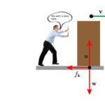
The answer has to do with acceleration and Newton’s second law of motion: F = ma (force = mass x acceleration).
Recall that the balls in recirculating linear bearings change direction as they move from the load-bearing zone to the recirculation zone. In order to do this, they must decelerate as they’re guided around the end cap by the recirculation mechanism. This deceleration produces a force on the recirculation elements—especially the bearing block end cap. The higher the velocity of the balls (based on the velocity of the bearing block), the greater the deceleration and the higher the forces on the end cap (back to F = ma).
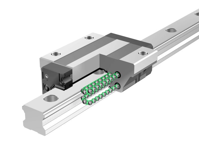
Image credit: Schaeffler Group Inc.
Understanding the principle of recirculation, you can see that there are two ways to achieve higher speeds with linear recirculating ball bearings: use an end cap capable of withstanding higher forces, or reduce the mass of the balls.
Most linear bearing manufacturers, indeed, offer recirculating ball bearings with reinforced recirculation mechanisms, including end caps. This is often the design for linear bearings labeled as “high speed,” with maximum speeds up to 5 m/s (16.4 ft/s).
Some manufacturers also offer high-speed linear recirculating bearings with ball chains (also referred to as ball separators, ball spacers, or caged balls) because they eliminate contact between balls—further reducing friction and heat—and ensure that each ball is supplied with constant and sufficient lubrication.
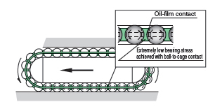
Image credit: THK
The other alternative is to reduce the mass of the balls, thereby reducing the forces imparted on the end caps during recirculation. To achieve this, some manufacturers offer linear bearing blocks with ceramic balls. Ceramic is used because it has a low mass-to-strength ratio, and it has good rolling properties when used on a steel surface. Linear bearings with ceramic balls can achieve maximum speeds up to 10 m/s (32.8 ft/s), but their dynamic load capacities are reduced by up to 30 percent when compared to similar bearings with conventional steel balls.
Next, we’ll look at factors that limit the speed of linear plain bearings.
Feature image credit: Federal Highway Administration

Leave a Reply
You must be logged in to post a comment.