Linear motion systems — consisting of a base or housing, a guide system, and a driving mechanism — are available in a wide variety of designs and configurations to suit almost any application. And because their designs are so varied, they’re often categorized according to key construction and operating principles. Case in point: The term “actuator” typically refers to a linear motion system with an aluminum housing that encloses the guide and drive mechanisms; systems referred to as “tables,” or “XY tables,” are commonly designed with a flat baseplate to which the guide and drive components are mounted; and “linear stage” or “linear translation stage” typically refers to a system similar in construction to a linear table but designed to minimize errors in positioning and travel.
Linear motion systems can exhibit three types of errors: linear errors, angular errors, and planar errors.
Linear errors are errors in positioning accuracy and repeatability, which affect the system’s ability to reach the desired position.
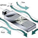
Angular errors — commonly referred to as roll, pitch, and yaw — involve rotation about the X, Y, and Z axes, respectively. Angular errors can lead to Abbé errors, which are angular errors amplified by distance, such as the distance between a linear guide (the source of the angular error) and the tool point of a measuring device. It’s important to note that angular errors are present even when the stage isn’t in motion, so they can have a negative effect on static operations such as measuring or focusing.
Planar errors occur in two directions — deviations in travel in the horizontal plane, which is referred to as straightness, and deviations in travel in the vertical plane, which is referred to as flatness.
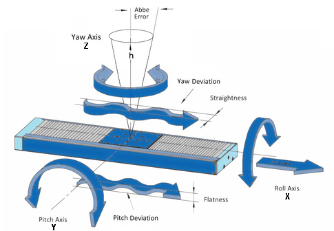
Image credit: PI USA
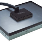
Although there are no rules or strict guidelines for what constitutes a linear stage, they’re widely recognized as the most precise category of linear motion systems. When a system is referred to as a linear stage, it’s generally understood that the system will provide not just high positioning accuracy and repeatability, but also low angular and planar errors. To achieve this level of performance, there are several principles that manufacturers generally follow in terms of construction and the type of components used in the stage design.

Image credit: Dover Motion
First, unlike other linear motion systems, which commonly use an aluminum extrusion or plate as the base, a linear stage begins with a precision-ground base. Stages designed for the highest levels of flatness, straightness, and rigidity often use a base made of steel or granite, although aluminum is used in some designs. Steel and granite also have lower coefficients of thermal expansion than aluminum, so they exhibit better dimensional stability in environments with extreme or varying temperatures.
The linear guide system also contributes to the straightness and flatness of travel, so the guide mechanisms of choice for a linear stage are high-precision profiled rails, crossed roller slides, or air bearings. These guide systems also provide very stiff support to reduce angular errors, which can lead to Abbé errors when there’s an offset between the origin of the error (the guide) and the point of interest (tooling point or load position).
While many types of linear motion systems use high-precision drive mechanisms, linear stages overwhelmingly use one of two technologies: a high-accuracy ball screw or a linear motor. Linear motors typically provide the highest level of positioning accuracy and repeatability, since they eliminate the compliance and backlash inherent in a mechanical drivetrain and coupling between the drive and the motor. For the special case of sub-micron positioning tasks, piezo actuators or voice coil motors are typically the drive mechanisms of choice, for their highly accurate, repeatable motion.
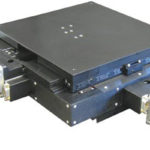
Although the term “linear stage” implies a single-axis motion system, stages can be combined to form multi-axis systems such as XY stages, planar stages, and gantry stages.
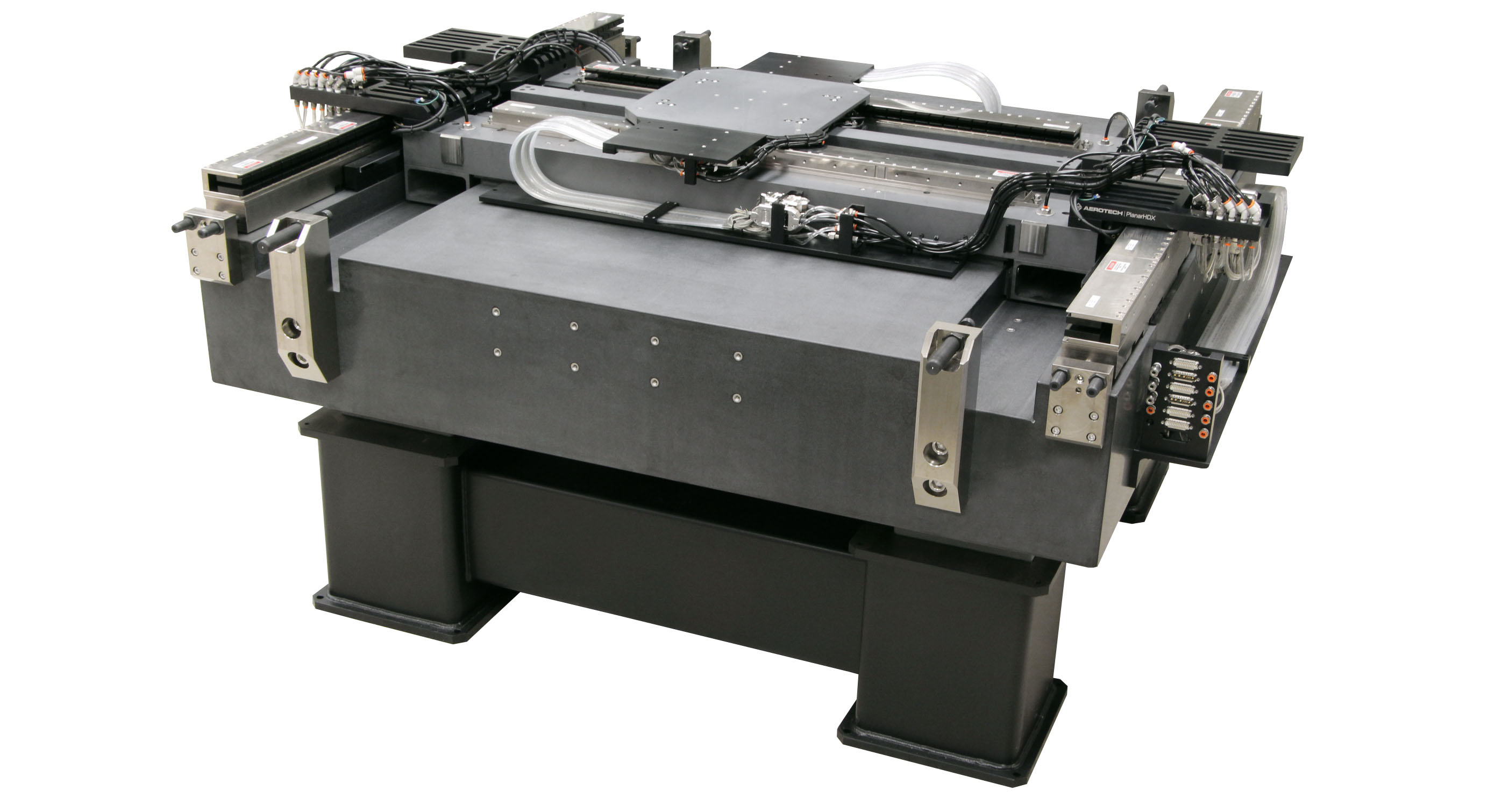
Image credit: Aerotech


Leave a Reply
You must be logged in to post a comment.