
Ball and lead screw assemblies are often driven by a motor connected in-line with the screw shaft via a coupling. While this mounting arrangement is simple and easy to service, the addition of a non-rigid mechanical component (the coupling) can introduce windup, backlash, and hysteresis — all of which affect positioning accuracy and repeatability. The coupling also adds length, reduces rigidity, and increases the inertia of the system. One way to eliminate these potential problems is to do away with the external coupling and integrate the screw directly into the motor.
Integrated motor and screw assemblies are available in various configurations and designs. The motor can be either a servo or a stepper type, and the screw can be a ball screw or a lead screw, although the most common configurations pair a lead screw with a stepper motor or a ball screw with a servo motor.
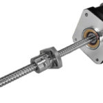
External motor-screw integration
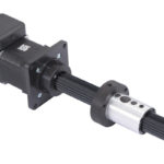
One of the most popular integrated designs uses a motor with a hollow shaft and integrates the lead screw directly into the motor. The screw is machined so that one end that mates to the hollow bore of the motor, and the machined end is either permanently fixed to the motor bore via welding or an adhesive, or secured with a fastener. Connecting the screw shaft to the motor bore via a fastener allows the components to be disassembled for maintenance and makes it possible to replace either component (rather than replacing the entire assembly), but this method can also experience loss of alignment and rigidity over time.
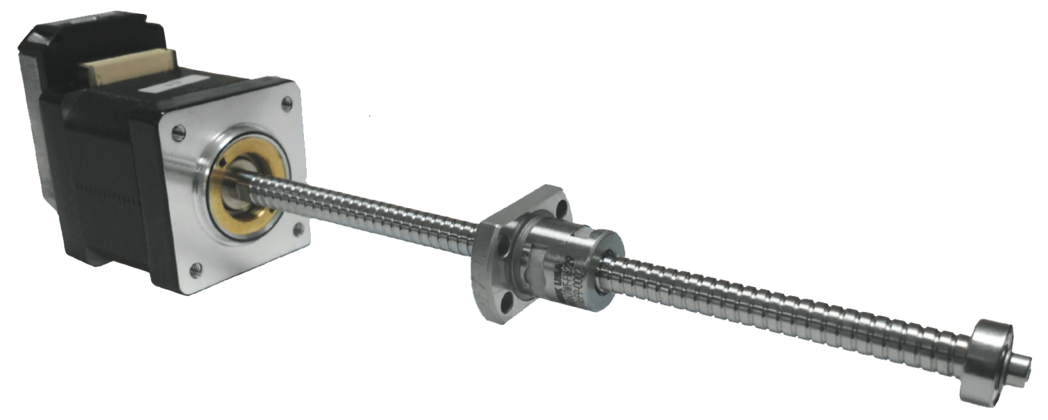
Image credit: NSK
Regardless of which method is used to connect the screw shaft to the motor, this method of motor-screw integration is typically referred to as an “external” design because the ball or lead screw nut remains external to the motor. Like a traditional screw-motor setup, the motor’s rotation causes the screw to turn, which advances the nut (and the load) along the length of the screw shaft.
Although applications with short strokes and light loads can sometimes operate without additional support for the screw (essentially a fixed-free arrangement) or without linear guides, most applications will require support for the opposite end of the screw and the use of linear guides to prevent radial loads on the screw.
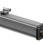
Non-captive motor-screw integration
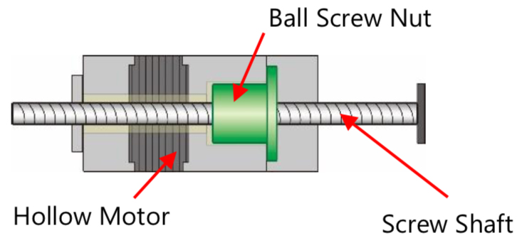
Image credit: KSS
In the non-captive method of integration, the ball or lead screw nut is integrated into the motor (or mounted to the face of the motor) and does not travel along the screw. Instead, the screw is prevented from rotating (typically by the attached load), and when the motor and nut turn, the screw travels linearly, back-and-forth “through” the motor-nut combination. In this configuration, the non-captive design provides a better stroke-to-overall length ratio, provided the design allows space for the screw to extend beyond the back of the motor.
Alternatively, if the screw is fixed so that it doesn’t travel, the assembly essentially becomes a driven nut design, where the motor’s rotation causes the motor-nut assembly to travel back-and-forth along the stationary screw. Like a conventional driven nut assembly, this configuration allows higher travel speeds, because screw whip is almost entirely eliminated. It also allows multiple motor-nut combinations to be mounted to the same screw shaft and driven independently.
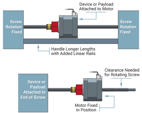
Image credit: PBC Linear
Captive motor-screw integration
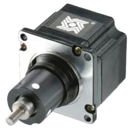
Image credit: Ametek
A variation of the above motor-screw combination is the captive design. Like the non-captive design, the nut is integrated directly into the motor, but a spline shaft is attached to the screw, preventing the screw from rotating and creating linear motion when the motor turns.
In this design, the screw extends and retracts from one end of the assembly and is not supported. The captive design is essentially a more compact version of the thrust rod style actuator, making it best suited for pushing or pressing applications where the load is guided and there is no radial force on the screw.
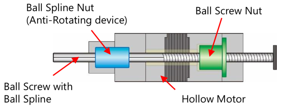
Image credit: KSS


Leave a Reply
You must be logged in to post a comment.