• Skip to primary navigation
  • Skip to main content
  • Skip to primary sidebar
  • Skip to footer

Linear Motion Tips

Covering Linear Motion Systems, Components and Linear Motion Resources

  • New
    • Editor’s blog
    • Industry news
    • Motion Casebook
    • Video
  • Applications
  • Slides + guides
    • Ball + roller guides
    • Track roller (cam + wheel) guides
    • Crossed-roller slides
    • Linear bearings
    • Plastic + composite guides
  • Drives
    • Ball + lead + roller screws
    • Belt + chain drives for linear
    • Rack + pinion sets
  • Actuators
    • Ball + leadscrew driven
    • Belt + chain driven
    • Linear motors
    • Mini + piezo + voice coil
    • Rack + pinion driven
    • Rigid-chain actuators
  • Encoders + sensors (linear) + I/O
  • Stages + gantries
  • Suppliers

What’s the difference between a ball screw spline and a traditional ball screw?

October 1, 2020 By Danielle Collins Leave a Comment

A ball screw spline is a combination of two components — a ball screw and a rotary ball spline. By combining a driving element (the ball screw) and a guiding element (the rotary ball spline), a ball screw spline can provide both linear and rotary motion, as well as spiral motion, in a highly rigid, compact design.


Components of a ball screw spline

Ball screw

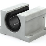
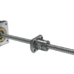
A ball screw uses recirculating steel balls in a precisely machined nut to drive a load to an exact position. In most designs, the screw is fixed at one or both ends, and the nut is prevented from rotating via a keyed housing or other anti-rotation setup. A motor drives, or rotates, the screw. But because the screw is constrained from moving linearly, the motion is transferred to the ball nut, which travels along the length of the screw shaft.

Another ball screw design incorporates radial angular contact bearings on the outer diameter of the nut, allowing the nut to be driven — typically via a belt and pulley assembly connected to a motor — while the screw remains completely stationary. When the motor turns, it rotates the nut, causing it to traverse the length of the screw. This setup is commonly known as a “driven nut” design.

Ball Nut Driven by Belt and Pulley System
A “driven nut” design uses a belt and pulley connected to a radial bearing assembly on the outer diameter of the ball nut.
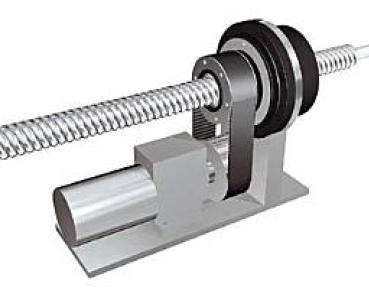
Image credit: SKF Group
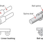
Ball spline

A ball spline is a type of linear guide system similar to the round shaft and recirculating ball bearing, but with spline grooves precisely machined along the length of the shaft. These grooves prevent the bearing — referred to as a spline nut — from rotating, while also allowing the ball spline to transfer torque.

One variation of the standard ball spline is the rotary ball spline, which adds a rotating element — gears, crossed rollers, or angular contact ball bearings — to the outer diameter of the spline nut. This allows the rotary ball spline to provide both linear and rotational movement.

Ball Splines
A rotary ball spline uses angular contact bearings (shown), crossed rollers, or gears on the outer diameter of the spline nut to produce rotary motion.
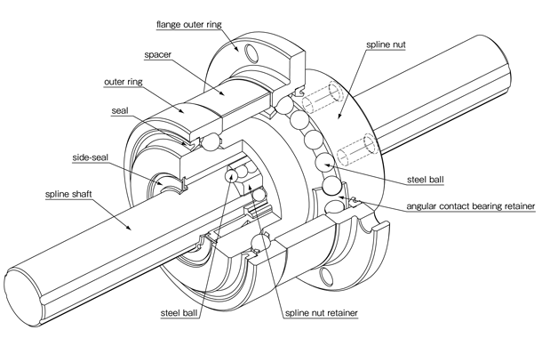
Image credit: NB Corporation of America

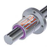
How a ball screw spline works

When a driven-nut type ball screw assembly is combined with a rotary ball spline, the resulting configuration is commonly referred to as a ball screw spline. The shaft of a ball screw spline has both screw threads and spline grooves along its length, with the threads and grooves “crossing” each other.

ball screw spline
A ball screw spline has both a ball nut and a spline nut, each with a radial bearing on its outer diameter.
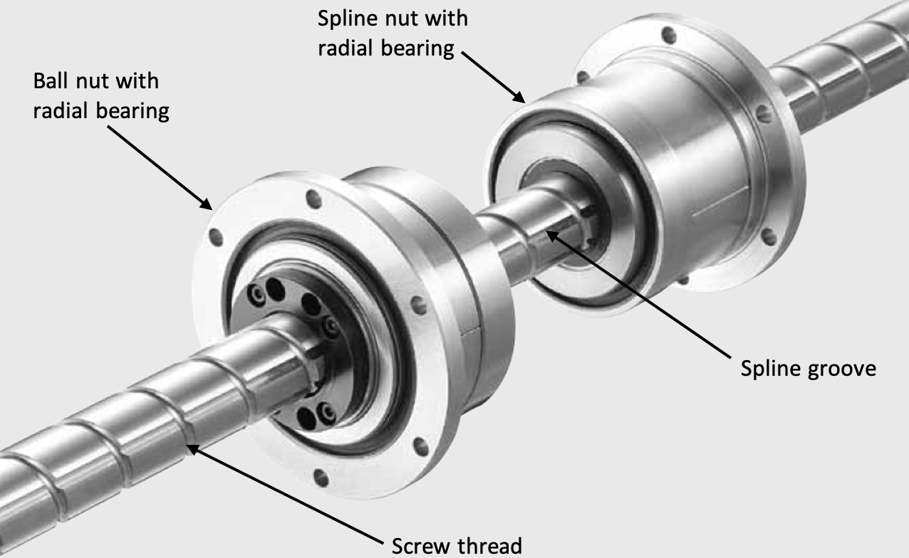
Image credit: Nippon Bearing

Three motions: linear, spiral, and rotary

Ball screw spline assemblies constrain both the ball screw nut and the ball spline nut from moving linearly. By driving the ball nut and the spline nut together or separately, three different types of motion can be produced: linear, spiral, and rotary.

To create linear motion, the ball nut is driven and the spline nut is held stationary. Since the ball nut cannot traverse linearly, the shaft traverses through the ball nut. However, the stationary spline nut keeps the shaft from spinning, so that the motion of the shaft is purely linear, with no rotation.

Alternatively, when the spline nut is driven and the ball nut is held stationary, the ball spline causes rotational motion, while the screw threads traveling through the stationary ball nut cause the shaft to travel linearly as it rotates, resulting in a spiral motion.

When both nuts are driven, the rotation of the ball nut essentially counteracts the linear motion caused by the ball spline, so the shaft rotates without any linear travel.
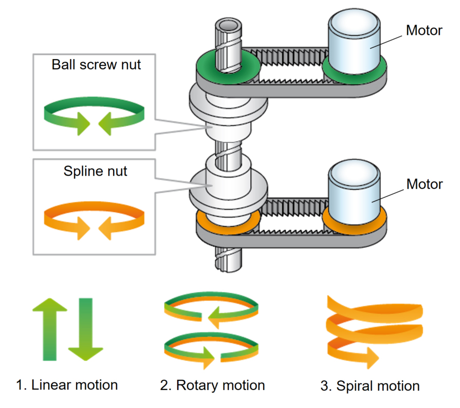
ball screw spline
In a ball screw spline assembly, the ball screw nut and spline nut can be driven separately or together to produce linear, spiral, or rotary motion.
Image credit: THK

You may also like:


  • Tips for mounting linear ball bearings: Pillow block housings

  • What options are there for integrated motor and screw designs?
  • rotating ball nut
    What are the benefits of a rotating ball nut (aka…
  • ball spline
    When should you use a ball spline?
  • Ball Splines
    What are ball splines and rotary ball splines?

Filed Under: Ball + lead + roller screws, Ball + leadscrew driven, Ball + roller guides, FAQs + basics, Featured

Reader Interactions

Leave a Reply Cancel reply

You must be logged in to post a comment.

Primary Sidebar

MOTION DESIGN GUIDES

“motion

“motion

“motion

“motion

“motion

“motion

“motion

“motion

“motion
Subscribe Today

RSS Featured White Papers

  • Identifying Best-Value Linear Motion Technologies
  • What are dual-motion hybrid actuators and where do they excel?
  • Considerations for adding Linear Guide Features to Industrial equipment

RSS Motion Control Tips

  • Miniature controllers from FAULHABER control a range of dc motors
  • Robotic bartender powered by Arduino-compatible controller and BLDC servo motors
  • What are double- and triple-stack hybrid stepper motors ?
  • PowerSTAR right angle gearmotor features advanced precision hypoid gearing
  • What are different ways to express a gear ratio?

Follow us on Twitter

Tweets by Linear_Motion

Footer

Linear Motion Tips

Design World Network

Design World Online
The Robot Report
Coupling Tips
Motion Control Tips
Bearing Tips
Fastener Engineering

Linear Motion Tips

Subscribe to our newsletter
Advertise with us
Contact us
About us

Follow us on TwitterAdd us on FacebookAdd us on LinkedInAdd us on YouTubeAdd us on Instagram

Copyright © 2021 · WTWH Media LLC and its licensors. All rights reserved.
The material on this site may not be reproduced, distributed, transmitted, cached or otherwise used, except with the prior written permission of WTWH Media.

Privacy Policy