
In its most basic form, a double ball nut is essentially two single ball nuts that have been tensioned against each other to induce preload. Three common methods for inducing preload in a double nut are:
- With a spacer ring between the ball nut halves
- With a spring between the ball nut halves
- By creating an offset in the lead
The geometry of double nuts differs from that of single nuts in that double nuts, when preloaded, produce two-point contact between the balls and raceways, whereas preloaded single nuts have four-point contact. This four-point contact causes differential slip, or partial sliding, which increases heat generation and results in premature wear. And depending on loading conditions, the four-point contact of single nuts can also reduce life expectancy.
Despite the fact that they incorporate two single nuts, double ball nuts do not have higher load capacities than single ball nuts. This is because the tension between the nuts forces them in opposite axial directions, so only one nut will take the load coming from a given direction.
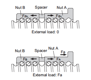
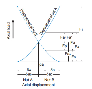
As the above illustration shows, both nuts experience a force, Fa0, due to the preload. When an external force, Fa, is applied to ball nut A, the resulting force on nut A becomes:
FA = Fa0 + (Fa – Fa’)
Fa0 = preload force
Fa – Fa’ = the amount of the applied force that exceeds the preload force
This can be approximated as:
FA = Fa0 + ½ * Fa
We’ll explore the equations for elastic deformation of each ball nut in a future post, but in short, both ball nuts experience some deflection caused by the preload. When an external force is applied, it causes nut A to deflect by an additional amount. Conversely, the deflection in nut B decreases by the same amount.
When a spacer ring is used in a double nut assembly, the amount of preload is determined by the thickness of the spacer. If the spacer is not perfectly flat, or if the two nut halves are not exactly perpendicular to the spacer, this preload method can cause inconsistency in the contact angle of the balls. However, when machined to a high tolerance, this design has consistent friction torque and produces extremely smooth motion.
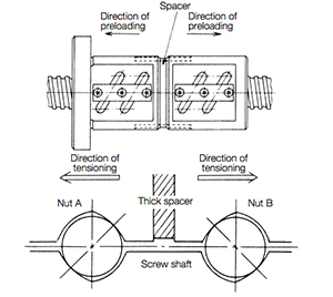
Image credit: Nidec Corporation
The use of a spring between the nut halves eliminates the concern of spacer flatness, but the maximum thrust force that can be applied is limited by the spring. If the stiffness of the spring is overcome by the thrust force, the spring will collapse and preload will be lost. However, with this method, wear has no effect on preload, since the spring adjusts to the given conditions.
The lead offset method differs in structure from the spacer and spring designs, but provides the same end result. In this method, an offset of the lead is produced during manufacturing. The offset is located approximately halfway down the nut body and produces preload via two-point contact of the balls. Lead offset ball nuts typically have fewer active ball grooves, which reduces load capacity, and therefore, dynamic life. However, the single housing makes the lead offset design more compact than designs that incorporate two separate ball nuts. Despite using only one nut body, some manufacturers refer to this nut type as a “double nut,” since it produces two-point contact of the balls with the raceways. For screws with multiple starts, a similar effect can be achieved by shifting the lead between thread starts, rather than shifting within a single thread start.
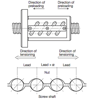
Image credit: Nidec Corporation
Feature image credit: THK

Leave a Reply
You must be logged in to post a comment.