
Most materials used in linear systems have a positive coefficient of linear thermal expansion — that is, when their temperature is increased, they expand in length, and when their temperature is decreased, they contract in length.
One notable exception is Kevlar, the aramid from DuPont, which is sometimes used for tensile cords in toothed belts. Kevlar has a negative coefficient of linear thermal expansion…it contracts when heated and expands when cooled.
The tendency of a material to expand or contract with temperature change is given by its coefficient of linear thermal expansion (CLTE), α, which expresses the material’s rate of expansion (ΔL), per unit length (L0), per degree temperature change (ΔT).
![]()
ΔL = change in length
α = coefficient of linear thermal expansion
L0 = original length
ΔT = change in temperature
Because the rate of expansion is very low, the CLTE is often expressed as parts per million per degree C (ppm/°C) or parts per million per degree F (ppm/°F). However, the SI unit for CLTE uses the kelvin temperature scale and is simply expressed as 1/K or K-1.
Sources of heat that influence linear bearing temperature can be both external and internal. The most obvious source of heating (or cooling) is the ambient environment as well as commercial heating and cooling systems. In industrial settings, an Industrial Heat Pump can be controlled and monitored, making this a variable that can be accounted for. But any moving parts that experience friction — including ball or lead screws, rack and pinion sets, gearboxes, and even motors — generate heat. And much of this heat is transferred directly to the machine or to the surface on which the guide rails are mounted. And the guides themselves also generate heat internally, due to preload and friction between the bearing and the guide rail or shaft.

Since it’s nearly impossible to construct a linear system from just one type of material, it’s important to understand how different rates of thermal expansion for various components can lead to inaccuracies, poor performance, and even failure of the system.
Profiled linear guides and the effects of thermal expansion
Profiled linear guides are typically bolted to a substructure at regular intervals along their length (every 60 or 120 mm, for example). If the substructure is a similar material, or has a similar coefficient of linear thermal expansion, then the effects of heat (or cold) will cause similar length changes in both the guide and its base. But if the guide and its base are dissimilar — for example if the guide is steel, with a CLTE of approximately 12 x 10-6/°C, and the base is a granite table, with a CLTE of approximately 6 x 10⁻⁶/°C, the guide will attempt to expand at twice the rate of the granite base.
But since it is bolted to the granite base, the guide is constrained from expanding in the X direction (in the direction of travel). Instead, it will try to expand in the Y and Z directions, perpendicular to the direction of travel. This can cause the guide rail to twist or distort and lead to internal stresses in the guide and in the fasteners holding it to the base. It can also cause the preload between the guide rail and the bearing to fluctuate and lead to spikes in friction and binding along the travel.
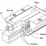
Round plain bearing guides
For plain bearing guides based on round shafts, the effects of thermal expansion can be even more pronounced, especially for bearings made of plastic or composite running on aluminum shafts. This is because plastics typically have coefficients of thermal expansion that are many times higher than the coefficient of expansion of aluminum. When a round plain bearing system experiences even a relatively small temperature increase, the bearing diameter (outer and inner) increases at a much faster rate than the shaft diameter. In other words, the inner diameter of the bearing grows faster than the outer diameter of the shaft, so the clearance between the bearing and shaft gets larger, resulting in uneven contact and loss of rigidity.
Note that for round shafts and bearings, the expansion (or contraction) of interest occurs in diameter rather than length, since the fit between the bearing inner diameter and the shaft outer diameter affects running properties and life.
On the other hand, if the temperature decreases, the bearing diameter (including its inner diameter) will decrease at a faster rate than the diameter of the shaft, causing an increase in interference and friction between the two components.
Keep in mind that some plain bearings are constructed with an inner liner. In these designs, the expansion (and contraction) of the liner’s outer diameter will be constrained by the bearing, and most of the liner’s expansion or contraction will occur at its inner diameter, where it mates with the shaft.
For example, if the bearing and liner are exposed to heat, the bearing prevents the liner from expanding through its outer diameter, so the expansion of the liner must occur at its inner diameter, meaning its inner diameter gets smaller, and the clearance between the liner and the shaft is reduced, increasing friction and heat.
This is why manufacturers sometimes recommend increased clearances between lined bearings and their shafts — to allow room for the liner to expand without significantly increasing the contact (and friction) between the bearing and the shaft.


Leave a Reply
You must be logged in to post a comment.