
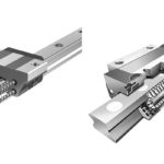
You’ve chosen a profiled rail and bearing for a high-precision application — machining, cutting, or metrology, for example. The bearing (aka carriage, or runner block) has good load capacity and rigidity, so it should provide long life and low deflection.
But when you integrate the assembly into your application, you notice that the system doesn’t travel as smoothly as you expected. Instead of smooth, precise movement, there are deviations, or pulses, in the travel, making it difficult to achieve the surface finish or measuring accuracy you need. You specified “precision” accuracy class for both the rail and the carriage, so what gives?
After some research, you find out that the profiled rail accuracy classes specifiy the allowable linear deviations, such as height and width, between the carriage and rail, but they don’t address rotational movements of the carriage. These rotational movements — roll, pitch, and yaw — can significantly degrade accuracy in applications where the motion of the carriage as it travels along the rail is critical.
Traditional profiled rail accuracy classes define five characteristics: the height and width tolerances of the rail and carriage assembly; the permissible differences in height and width of multiple carriages on the same rail; and the parallelism between the rail and carriage reference surfaces.
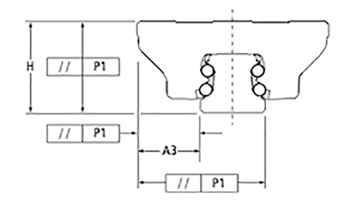
Image credit: Thomson Linear
But as the carriage travels along the rail, it also experiences rotational deviations, in the form of rolling (rotation around the X axis), pitching (rotation around the Y axis), and yawing (rotation around the Z axis). These rotational deviations aren’t covered by the standard profiled rail accuracy classes, but manufacturers are beginning to address them.
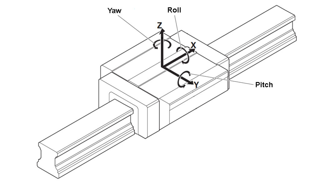
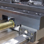
Image credit: Bosch Rexroth Corp.

Image credit: Schneeberger Group
In a recirculating linear bearing, as the balls (or rollers) transition into and out of the load-bearing zone, they make the transition from being unloaded to being loaded (or vice-versa) not in a smooth, linear fashion, but in pulses. This effect on the load-bearing balls causes pronounced rotational movements of the carriage.
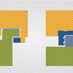
To reduce these dynamic motions, manufacturers have put significant effort into optimizing ball (or roller) recirculation. Two common methods are the use of a flexible steel insert to guide the balls from the non-loaded to the loaded state and dampen the forces that occur during the transition, or a longer entry zone to allow a more gradual transition from the non-loaded to the loaded condition.
Regardless of the method used, smoothing the transition of the balls (or rollers) through the entry and exit zones of the carriage reduces the pulsations that cause rotational movements. Improving the pulsating nature of the ball transition also reduces friction forces in the carriage, and more importantly, variations in friction forces that can cause the system to overshoot or undershoot position in highly sensitive applications.
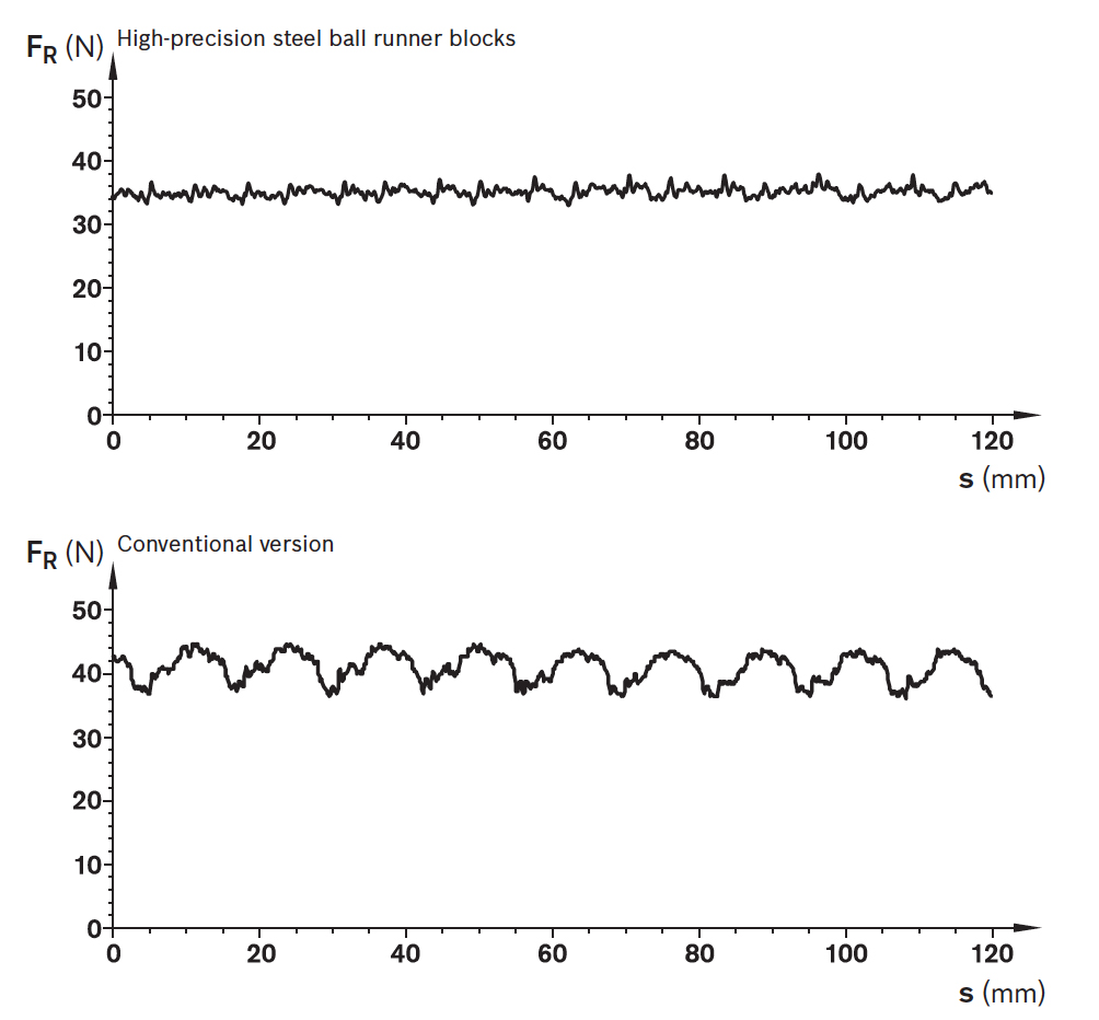
Image credit: Bosch Rexroth Corp.
When profiled rail guides were first introduced in the 1970’s, they became the preferred choice for machine tool applications, often replacing traditional boxway or dovetail guides, thanks to lower friction due to rolling (rather than sliding) contact. They were also found to be a good choice for applications that required high load capacities and high rigidity for strokes longer than about a meter — the length at which crossed roller slides become impractical.
However, these benefits came at the cost of travel smoothness, so for highly sensitive machining, cutting, and measuring applications, crossed roller slides, boxway or dovetail slides, or even air bearings were still the guide systems of choice. But with improved recirculation methods, profiled rail guides can now rival the travel smoothness and stability that were once only achievable with sliding or hydrostatic technologies.


Leave a Reply
You must be logged in to post a comment.