by Tony Chou, General Manager, Chieftek Precision USA
Linear motors deliver superior output, so excel in medical equipment, industrial automation, packaging, and semiconductor manufacturing. What’s more, new linear motors address the cost, heat, and integration complexity of early versions. To review, linear motors include a coil (primary part or forcer) and stationary platform sometimes called a platen or secondary. Subtypes abound, but the two most common for automation are brushless ironcore and ironless linear motors.

Linear motors generally outperform mechanical drives. They have unlimited lengths. Without the elasticity and backlash of mechanical setups, accuracy and repeatability are high and stay that way over the life of the machine. In fact, only the guide bearings of a linear motor need maintenance; all other sub-components are wear-free.

Where ironcore linear motors excel
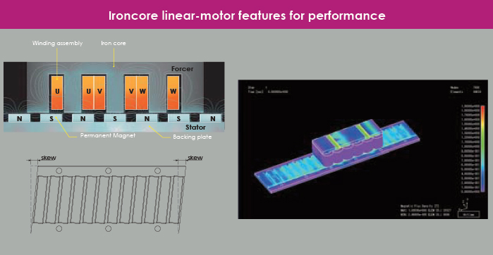
Ironcore linear motors have primary coils around an iron core. The secondary is usually a stationary magnet track. Ironcore linear motors work well in injection molding, machine tool, and press machines because they output high continuous force. One caveat is that ironcore linear motors can cog, because the magnetic pull of the secondary on the primary varies as it traverses the magnet track. Detent force is to blame here. Manufacturers address cogging in several ways, but it’s problematic where smooth strokes are the main objective.

Even so, ironcore linear-motor advantages abound. Stronger magnetic coupling (between iron core and stator magnets) makes for high force density. So, ironcore linear motors have higher force output than comparable ironless linear motors. In addition, these motors dissipate a lot of heat because the iron core sheds coil-generated heat during operation — reducing coil-to-ambient thermal resistance better than ironless motors. Finally, these motors are easy to integrate because the forcer and stator directly face each other.

Ironless linear motors for quick strokes
Ironless linear motors have no iron in their primary, so are lighter to output more dynamic motion. The coils are embedded in an epoxy plate. Most ironless linear motors have U-shaped tracks lined on the inner surfaces with magnets. Heat buildup can limit thrust forces to less than those of comparable ironcore motors, but some manufacturers address this issue with innovative channel and primary geometry.

Short settling times further boost the dynamics of ironless linear motors to make quick and accurate moves. No inherent attractive forces between the primary and secondary means ironless linear motors are also easier to assemble than ironcore motors. Plus their support bearings aren’t subject to magnetic forces, so usually last longer.

Note that linear motors have trouble on vertical axes and in harsh environments. That’s because without some braking or counterweight, linear motors (which are inherently non-contact) let loads fall during power-off situations.

In addition, some harsh environments can generate dust and shavings that stick to linear motors, especially in operations machining metal parts. Here, ironcore linear motors (and their magnet-filled track) are most vulnerable. Some actuators incorporate ironcore or ironless linear motors and a dustproof design to work in such environments. The latter eliminates the problems associated with bellows that traditionally protect linear axes.

When to pick integrated linear-motor actuators
The direct-drive nature of linear-motor actuators boosts productivity and system dynamics for myriad industrial applications. Some linear-motor based actuators also include encoders for position feedback … to make linear motors easy to use, even compared to belt and ballscrew-based systems. Some of these actuators tightly integrate the linear motor, guide, and optical (or magnetic) encoder to further boost power density.

The encoder in some actuators installs horizontally so its position is unaffected by external impact. Some such arrangements can run to 6 m/sec with acceleration to 60 m/sec2 using a 230-Vac input. Modules with travel exceeding two meters are possible. Standard offerings usually include a magnetic encoder for position feedback, though optical encoders are available for higher precision. Other options include multi-slider setups as well as complete X-Y and gantry systems.
Compared to traditional ballscrew modules, linear-motor-based actuators offer better precision and velocity — even under many thrust output conditions — thanks to direct driving. Tighter integration also boosts productivity and reliability. Some such actuators include the linear motor itself, a base, and wide linear guide supporting an aluminum slider and optical scale for position feedback. Where the linear motor is ironless, it can pair with an aluminum slider to form a lightweight design that quickly accelerates.
Some compact linear-motor actuators also include sliders with built-in lubrication pads for environmentally friendly lubrication. Here, the runner-block ends sport hermetically sealed grease injectors to deliver raceway lubrication via steel ball circulation. In some cases, optional lubrication pads add lubrication for long-term operation with less maintenance, especially on axes that make short strokes.

Ironless linear motors inside some actuators also exhibit no cogging, so the axis can make stable moves when moving slowly or quickly. With some designs, repeatability with an optical linear encoder is 2 mm. Some actuators are even available in strokes from 152 to 1,490 mm with straightness from 6 to 30 mm.
Special example: Cleanroom applications
One last option particularly suitable for applications with short strokes and high cycle rates are linear-motor actuators in which the moving parts are the magnets and rail. Here, there aren’t issues with moving cables causing disconnections. Nor are there problems with dusty environments. In fact, the actuators work well in vacuum environments and cleanrooms. That’s because the coils are fixed, so heat easily dissipates to mounting structures. Some such linear-motor actuators output continuous force to 94.2 or 188.3 N and peak force to 242.1 or 484.2 N — accepting continuous current of 3.5, 7, or 14 A depending on the version. Strokes reach 430 mm.
Parameters to specify linear-motor stages
When specifying actuators or stages based on linear motors, consider the following criteria for each portion of the design’s motion profile:
• What is the known motion condition?
• What is the load’s mass, system mass, effective stroke, moving time, and dwell time?
• What’s the drive condition, maximum output voltage, continuous and peak current?
• What kind of encoder resolution does the setup need? Should it be analog or digital?
• Into what kind of working environment will the actuator or stage work? What will be the room temperature? Will the machine be subject to vacuum or clean room conditions?
• What are the application’s requirements for motion precision and positioning accuracy?
• Will the linear-motor actuator or stage move loads horizontally, vertically, or at an angle? Will the setup mount to a wall? Is it subject to space constraints?
Answering these questions will help design engineers identify the most appropriate linear-motor iteration for a given piece of machinery.
Chieftek Precision
www.chieftek.com


Leave a Reply
You must be logged in to post a comment.