
A large percentage of electromechanical linear motion applications—including ball and lead screw drives, rack and pinion drives, and linear actuators—use one of two motor technologies: servo or stepper. A servo motor is a closed-loop device, meaning it incorporates an encoder that monitors the actual motor position and feeds this information back to the drive, which compares it to the commanded position and makes any necessary adjustments. A stepper motor, on the other hand, is primarily an open-loop device, without a feedback mechanism to ensure that the actual position matches the target position. For applications that don’t require position feedback, stepper motors offer excellent performance at a lower price and with simpler control schemes than servo motors.
Basics of stepper motor construction
As their name implies, stepper motors move in discreet steps, known as the step angle, which usually ranges from 90 degrees (360° / 90° per step = 4 steps per revolution) to 0.75 degrees (360° /0.75° per step = 500 steps per revolution). Their basic construction consists of an outer stator and an inner rotor. The design of the rotor depends on the type of stepper motor being discussed, but the stator is similar between the various types of stepper motors, with uniform teeth around its perimeter and containing a specified number of poles. Poles are simply magnetic sections of the stator, and each pole has a winding that is connected to the pole opposite it on the stator. Thus, the opposing poles are magnetized with the opposite polarity when current is applied to the windings.
These pole pairs make up the winding phases, with most stepper motors being either 2-phase or 5-phase design. There can also be multiple pole pairs per phase; for example, a 2-phase stepper motor may have 3 pole pairs (6 poles) in each phase, for a total of 12 poles.
Stepper motor types
There are three general stepper motor designs: variable reluctance, permanent magnet, and hybrid. Regardless of the design, stepper motors have several performance characteristics in common. First, they produce high torque at low speeds, with maximum torque available when the rotor is stationary, making them good for applications that require holding a load in place. Second, a stepper motor’s speed is directly related to the frequency of the input pulses, making it easy to achieve and control a wide range of running speeds. Stepper motors also have a noncumulative positioning error, so if the specified error is ± 5°, regardless of whether the motor completes one step or one hundred steps, its final position will be within ± 5° of the intended position.

Variable reluctance
Variable reluctance steppers have a rotor made of soft iron. Both the stator and the rotor are toothed, but the rotor has fewer teeth than the stator to ensure that only one set of stator and rotor teeth aligns at any time. When the stator phases are energized, the iron rotor teeth align with the energized stator teeth, minimizing the reluctance (which is analogous to resistance in an electrical circuit) of the magnetic field.

Image credit: allaboutcircuits.com
Variable reluctance designs produce moderate torque and have large step angles, but they do not experience detent torque (see below) since their rotors are passive (non-magnetized). In general, variable reluctance steppers are the least expensive type of stepper motor.
Permanent magnet
Permanent magnet steppers have permanent magnet rotors and operate when a stator phase (pair of opposite poles) is energized and an electromagnetic field is created. The N pole of the magnetic rotor is attracted to the S pole of the phase, and vice-versa, causing the rotor to turn.
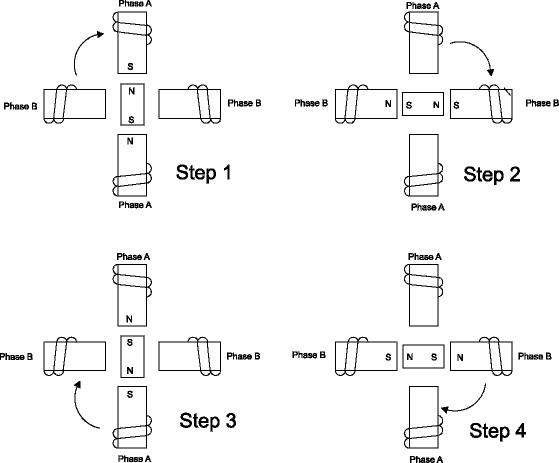
Image credit: PC Control Ltd.
Permanent magnet steppers have medium step angles and produce high torque. They also exhibit good holding torque when the rotor is stationary, without creating excess heat. When the coils are not energized, they exhibit residual torque (also referred to as detent torque) as a result of the magnetic flux between the rotor and stator. This is useful for holding a load in position with power off.
Hybrid
Hybrid stepper motors take features from both of the above designs, using a permanent magnet rotor with iron teeth. The rotor of a hybrid motor is typically two parts, with one part magnetized N and the other part magnetized S. The teeth of each rotor section are offset by ½ tooth pitch, so if each section has 50 teeth (poles), the rotor will be said to be 100-pole. The stator typically has two phases, which are offset by ¼ tooth pitch.

Image credit: allaboutcircuits.com
In this example, the combined stator and rotor tooth designs results in 200 steps per revolution, giving the hybrid motor a small step angle, particularly when compared to variable reluctance or permanent magnet designs. Hybrid stepper motors also have higher torque capabilities and more holding and detent torque than other designs.
Application Considerations
As the speed-torque curve above shows, stepper motor torque drops off rapidly as speed increases. In addition, stepper motors draw full current regardless of their speed (whether at standstill or moving), which results in high heat generation. Although stepper motors are inherently open-loop, they can be operated in a closed-loop configuration with the addition of an encoder. However, this somewhat negates the low-cost and ease-of-use characteristics that make them a desirable choice for many applications.
Feature image credit: Oriental Motor U.S.A. Corp

Thanks for explaining that the three general motor designs all produce torque at low speeds. My son is looking to produce a lot of torque for a science experiment. Step motors sound like a good way we could produce high torque for the experiment without generating a fast speed.