
Image credit: Rollon Corp.
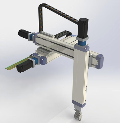
Cartesian robots operate in two or three axes along the Cartesian coordinate system of X, Y, and Z. While SCARA and 6-axis robots are more widely recognized, Cartesian systems can be found in nearly every industrial application imaginable, from semiconductor manufacturing to woodworking equipment. And it’s no surprise that Cartesians are so widely deployed. They’re available in seemingly limitless configurations and are easily customized to meet the exact application parameters.
While Cartesian robots have been traditionally designed and built in-house by integrators and end-users, most linear actuator manufacturers now offer pre-engineered Cartesian robots that significantly reduce engineering, assembly, and startup time compared to building a system from scratch. When selecting a pre-engineered Cartesian robot, here are three things to keep in mind, to ensure you get the best-fit system for your application.
Orientation
Orientation is often dictated by the application, with a key factor being whether the parts need to be handled, or the process needs to take place, from above or below. It’s also critical to ensure that the system doesn’t interfere with other stationary or moving parts and doesn’t pose a safety hazard. Fortunately, Cartesian robots are available in many different X-Y and X-Y-Z configurations to meet application and space restrictions. Within the standard multi-axis orientations, there are also options to mount the actuators upright or on their sides. This design choice is usually made with stiffness in mind, since some actuators (especially those with dual guide rails) have a higher stiffness when mounted on their sides.
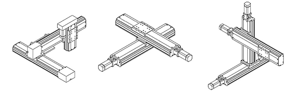
Image credit: Servo Vision Co., Ltd
For the outermost axis (Y in an X-Y configuration, or Z in an X-Y-Z configuration), the designer has a choice of whether the base will be fixed with the carriage moving, or the carriage fixed with the base moving. The primary reason to fix the carriage and move the base is interference. If the actuator protrudes into a work area and needs to move out of the way while other systems or processes move through, then moving the base allows a significant part of the actuator to be retracted and vacate the space. It does, however, increase the moved mass and inertia, so this should be taken into account when sizing gearboxes and motors. And cable management has to be designed so that it can move with the axis, since the motor will be moving. Pre-engineered systems take these issues into account and ensure that all components are designed and sized properly for the exact orientation and layout of the Cartesian system.
Load, stroke, and speed
These three application parameters are the basis on which most Cartesian robots are selected. An application requires a certain load to be moved a specific distance, within a given time. But they’re also interdependent—as the load increases, maximum speed will eventually begin to decrease. And stroke is limited by the load if the outermost actuator is cantilevered, or by speed if the actuator is ball screw driven. This makes sizing a Cartesian system a very complex undertaking.
To simplify the design and sizing tasks, Cartesian robot manufacturers typically provide charts or tables that give the maximum load and speed for specified stroke lengths and orientations. However, some manufacturers state maximum load, stroke, and speed capabilities that are independent of each other. It’s important to understand if published specifications are mutually exclusive, or if the maximum load, speed and stroke specifications can be achieved together.

Precision and accuracy
Linear actuators are the basis of a Cartesian robot’s precision and accuracy. The type of actuator—whether it has an aluminum or steel base, and whether the drive mechanism is belt, screw, linear motor, or pneumatic—is the main determinant of accuracy and repeatability. But how the actuators are mounted and fastened together also has an effect on the robot’s travel accuracy. A Cartesian robot that is precision-aligned and pinned during assembly will generally have a higher travel accuracy than a system that is not pinned, and will be better able to maintain this accuracy over its lifetime.
In any multi-axis system, connections between axes aren’t perfectly rigid, and numerous variables affect the behavior of each axis. This makes travel accuracy and repeatability difficult to calculate or model mathematically. The best option to ensure a Cartesian system meets the required travel accuracy and repeatability is to look for systems that have been tested by the manufacturer, with similar loads, strokes, and speeds. Most Cartesian robot manufacturers recognize this as a key concern for users, and have tested their systems in order to provide “real-world” data on performance in various applications.
Pre-engineered Cartesian robots provide significant savings over robots that are designed and assembled in-house. The time required to size, select, order, assemble, start up, and troubleshoot a multi-axis system can be hundreds of hours, and pre-engineered systems reduce this to just a few hours of selection and start-up time. And the range of configurations, guide types, and drive technologies available in manufacturers’ standard offerings means designers and engineers don’t have to compromise on performance or pay for more capability than the application requires.
Feature image credit: RobotWorx

Leave a Reply
You must be logged in to post a comment.