
Linear guide rails and bearings offer high stiffness and good travel accuracy. And they can support not only downward, upward, and side loads, they can also withstand overhung, or moment loads. Of course, the larger the linear rail and bearing system, the more moment capacity it has, but the arrangement of the bearing raceways—face-to-face or back-to-back—also influences the amount of overhung load that it can support.
While the face-to-face design (also known as the “X” arrangement) provides equal load capacities in all directions, it results in a shorter moment arm along which overhung loads are applied, which reduces moment load capacity. The back-to-back arrangement (also known as the “O” arrangement) provides a larger moment arm and gives higher moment load capacities.
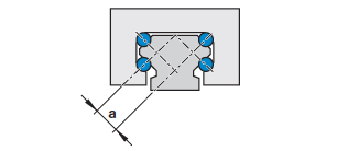
Image credit: Bosch Rexroth
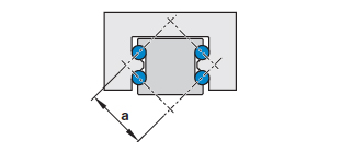
Image credit: Bosch Rexroth
Even with the back-to-back arrangement, however, linear guides have a relatively short distance between the raceways (essentially equal to the width of the rail), which limits their ability to handle roll moments, which are caused by loads overhung in the Y direction. To counter this limitation, using two rails in parallel—with either one or two bearings on each rail—allows the roll moment to be resolved into forces on each bearing block. Since linear bearings have much higher capacity for forces than for moments (especially roll moments), bearing life can be significantly increased. Another benefit of using dual guide rails and allowing moments to be resolved into forces is that linear bearings generally deflect less under pure forces than under moment loads.
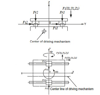
Image credit: NSK Ltd.

Image credit: NSK Ltd.
Many linear actuator designs include two rails in parallel, with the drive mechanism—belt, screw, or linear motor—incorporated between the rails. While it’s not imperative that the drive be centered between the guide rails, doing so helps ensure even loading on all of the bearings, and reduces cogging, or uneven drive forces on each rail and bearing set. This arrangement also reduces the height of the actuator, making it relatively compact given the high load and moment capacity provided by the dual guide rails.
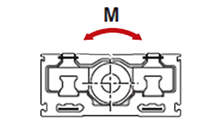
Image credit: Bosch Rexroth
Recirculating bearings (bushings) that ride on round shafts are unable to handle roll moments. This is why most linear bushing applications require that two shafts be used in parallel.

Leave a Reply
You must be logged in to post a comment.