Feedback options for linear motors and direct-drive torque motors abound. The most common employ optical, magnetic, capacitive, or inductive measurement. Here we explain how the key application parameters of precision, cost restrictions, and insensitivity to mechanical characteristics and environment dictate which technology is most suitable.
 By Steffen Preg | CEO • SIKO Products Inc.
Machines operate most efficiently and precisely when their axes are well controlled. Encoders in particular excel where precise motion tracking is necessary. These can take the form of rotary and linear motor feedback built into the drive frame to measure velocity and motor position. The most suitable encoder type and model economically satisfies requirements for precision and ruggedness.

Consider optical feedback — the subtype that’s been in the market longest. Optical-based feedback remains the gold standard for accuracy. Only since the early 2000s have magnetic, inductive, and capacitive offerings been commercially available for industrial applications. These other technologies don’t tend to deliver the accuracy of optical systems but are more cost effective and rugged and reliable where dust, liquids, vibration, and shock are involved. In fact, magnetic systems are particularly cost effective.
As we’ll explore in more detail, motion axes with longer-than-average strokes benefit from the price advantage of magnetic-based feedback over other measurement technologies. While capacitive-based feedback is most economical of all (due to lower material costs) magnetic options have maximum robustness. That’s especially true for applications exposed to humidity — and implementation of capacitive systems requires complex and expensive protective housings.
Motion applications with significant exposure to shock, vibration, dirt, or lubricants are inappropriate for fragile and sensitive optical-based feedback. The magnetic insensitivity of optical-based feedback does preclude other options where that’s an issue — especially on linear axes in the machine tool and medical industries. But the percentage of applications for which magnetic interference is an issue is quite small; typically, the magnetic field around an axis must be five times that of the magnetic feedback device to pose an interference problem. This is also quite rare as direct-drive and linear-motor manufacturers (for the sake of energy efficiency) have worked to make their motors’ fields as concentrated as possible in volume between the rotor and stator (or linear forcer and platen).
Basics of direct-drive motors
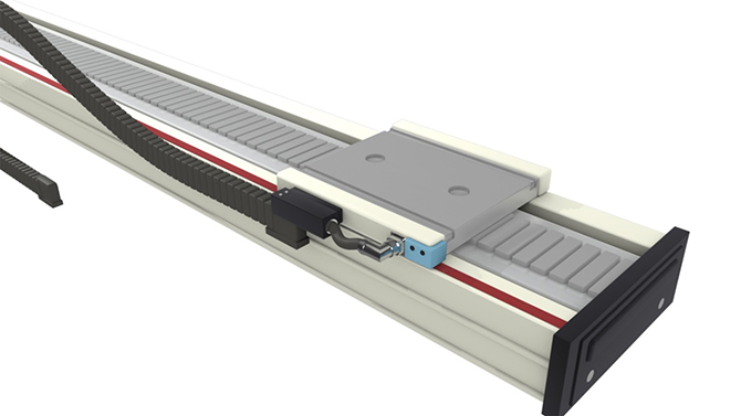
Direct-drive motors are so called for how they directly connect to the load with no intermediate gear or rotary-to-linear mechanism. Rotary direct drives (also called torque motors) are increasingly common in robotics. Linear direct drives (in the form of linear motors) are indispensable on positioning drives for machine tools and other axes needing top accuracy of path and constant velocity. In fact, linear motors impart a good force-to-mass ratio and unbeatable synchronization of axes.
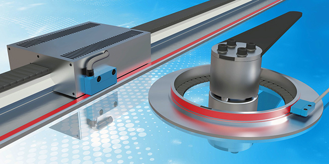
Most linear motors today include permanent-magnet arrays and a coil through which ac power is applied. The alternating field prompts the coil to advance through the varied magnetic field — or the other way around depending on what is fixed mechanically. Where the coil is integrated into a carriage, it moves along the magnet track while riding twin linear rails.
In contrast, torque motors for rotary axes are suitable for applications needing high torque and precise synchronization. These rotary direct drives work just like any other motor, but as a rule include a hollow center through which cables, compressed air lines, and other design elements pass or mount. Both rotary and linear direct drives necessitate feedback.
Motion-feedback requirements
Motor feedback is catchall term for position feedback on linear and rotary systems that include a controller, drive (to feed electrical power to the motor), and the motor itself. In such setups, the measurement system communicates information about travel direction, velocity, and precision with the controller.
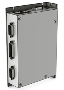
Key measures of a motor feedback systems are accuracy and repeatability. Usually (though not always) longer axes tend to need less precision … and magnetic-based feedback is often most suitable.
As we’ve mentioned, another key measure of a motor feedback system is ruggedness. This parameter often precludes technologies altogether. Case in point: The copious water required to cool tools in glass working renders optical and capacitive measurement systems (so sensitive to humidity) inappropriate — and only inductive or magnetic solutions are possibilities.
Besides these design objectives, another consideration for feedback is the motor-to-controller communication in use … as well as whether the feedback system should be incremental or absolute. Incremental systems are sometimes far more accurate than other offerings; Incremental outputs are also faster for control purposes. However, they necessitate a reference position upon initial energization to ensure the motor starts from a specified position. Such reference travel is unnecessary for absolute measurement systems. SIKO absolute encoders offers both incremental and absolute operation to deliver the benefits of both types of feedback.
Another consideration for rotary applications is the maximum shaft diameter, which can preclude certain feedback systems. Magnetic-based feedback options can handle large shaft sizes with an array of sealing options.
Astounding motion-controller technological advances over the last 15 or so years have spurred demand for increasingly advanced motor feedback. That’s especially true for modern controllers that can now serve in cost-efficient systems that basically run motors in absolute steady-state conditions.
Open and enclosed feedback modules
Open measurement systems are those without encapsulation or mechanical connection to the drive. These are most common, as they reduce part counts and give design engineers more installation options. In contrast, enclosed feedback systems encase the scale and sensor unit — for less adaptability but more ruggedness — including elements such as lip seals to prevent dirt ingress, for example. Such closed feedback systems are slightly more costly but indispensable in machine-tool builds and elsewhere.
Most all magnetic, capacitive, and inductive feedback systems come in open versions … with the added benefit of contactless operation for no wear on the scale and sensor unit. Optical feedback offerings are also non-contacting, with one exception — those designs with glass scales using a split mechanical housing for protection.
More about optical feedback
Optical systems based on light and glass scales differ from those based on from epi-illumination or laser technology. These track position using the Talbot effect: When electromagnetic wave signals incident upon a surface grated for diffraction, that grating’s image repeats at regular distances somewhere away from its plane. Where employed for motion sensing, this brightness distribution is measured by a read head. The grid behind the sensor head is exposed to monochrome electromagnetic waves for wider light distribution behind the grating. Resulting position values then go onward to controls as A, B, R digital-count pulses.
As a rule, laser-based systems use a thin metal strip as the scale. Many such scales are flexible enough to allow winding or coiling. This is an advantage over rigid yet fragile glass scales.
But glass-scale systems can be designed very precisely. Measurement accuracies to 3 µm or better are possible … and with such small error per meter of travel, glass-scale-based feedback excels on shorter linear axes. (Axes many meters long would necessitate prohibitively expensive transport and installation of long glass rods.)
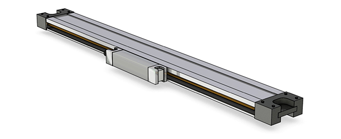
As mentioned earlier, a drawback of glass scales is their intolerance of mechanical impact, shock, and vibration. When used under such conditions, such scales require protective measures to prevent shattering. But the benefits of optical scales abound: The accuracy of many optical sensors reach ±5 mm and resolutions are to 0.05 mm. Optical-scale gradations (which partially define accuracy) are commonly to 20 mm. Then finer values are interpolated in sensor electronics and further processed by a system controller. High dynamics and the ability to return high-precision feedback with unbeatable accuracy, repeatability, and resolution even on very fast-traveling axes are key benefits of optical systems.
Another advantage of optical systems is insensitivity to magnetic disturbances. Consider how linear motors generate electromagnetic fields capable of degrading the signals of magnetic sensors if the sensor head and tape are installed too close to the motor. Avoiding this issue with magnetic sensors is easy — by using a shield or maintaining a defined safety clearance between motor and sensor … but again, this is not a design concern at all with optical-based feedback.
Optical measurement systems do suffer from sensitivity to dust, oils, and fats in the environment, as well as condensation on the scale where high humidity combines with temperature fluctuations. Protective housings can indeed prevent dirt and condensation from settling on the sensor but incur added cost.
Generally speaking, optical sensors cost about twice that of magnetic sensors … and the magnetic scale for an especially long axis might be about 60% cheaper than a comparable optical scale.
Magnetic measurement systems
With magnetic measurement systems, the sensor travels sans contact over a magnetic tape (sometimes called a code strip) applied to a steel carrier a few tenths of a millimeter thick. This scale is magnetized with pole pitches to spur generation of digital signals when a read head passes over these magnetic poles and scans them. The read head recognizes the tape’s divisions and converts the resulting data into high-resolution path information for control electronics to use in adjusting servo commands.
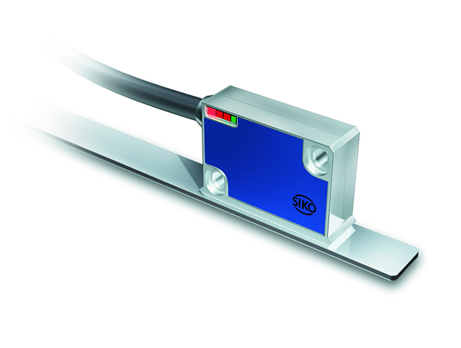
Consider one application — that of gantry drives with very long linear motors. Such designs must travel very quickly from one point to another but accuracy and precision requirements aren’t particularly strict. Here, one well-suited magnetic-sensing technology is that of a read head that uses the motor’s magnets as the linear scale.
Magnetic systems (just like inductive systems, which we’ll explore shortly) are resistant to dirt, oils, and humidity. In fact, magnetic scales can even work in areas of a machine subject to oil baths. Magnetic-based feedback also withstands shock and vibration for applicability in the most challenging designs — on off-highway and mobile equipment operating outdoors, for example. Magnetic measurement technology can also survive harsh applications such as stone and glass working. What’s more, the flexibility of the magnetic tapes means it can be shipped and stored coiled in rolls and then cut to size as needed.
Because the scale and even the mode of operation are so resilient, magnetic sensing lets design engineers mount the scale and read head fairly far apart if needed — even to several millimeters. This isn’t possible with other systems … for example, optical systems have such a delicate grid structure that the distance between the scale and head should never exceed a few tenths of a millimeter. While inductive technology has scale divisions of one millimeter to also allow wider scale-to-head distances, its read electronics tend to be bulkier than those of magnetic systems.
Drawbacks of magnetic systems are that they have lower absolute accuracy, resolution, and repeatability than optical designs. As mentioned, magnetic sensors are also sensitive to external magnetic sources of interference.
More on feedback based on capacitive means
Capacitive-based motion feedback is based on interactions between two mutually chargeable plates. Position changes between a printed circuit board (PCB) scale and read head prompt the generation of an electric signal for use by a controller. Such feedback operation is applicable to linear motion but limited by scale length. That’s why capacitive-based feedback is far more common on rotary axes driven by torque motors. In fact, they’re often used where it’s too costly or complicated to integrate an optical glass scale into a motor shaft or rotor.
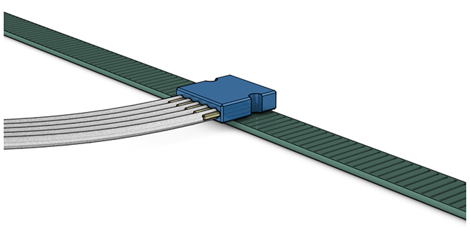
The main strength of capacitive-based feedback systems is cost effectiveness. That’s because the materials in capacitive sensors are inexpensive. In addition, capacitive sensors are designed to fit on specific rotary motor types — though this also tends to restrict their use with only a few motor-construction types.
The serious disadvantage of capacitive systems is their sensitivity to humidity. That’s why capacitive sensors are inappropriate for designs subject to washdown or where water is used to cool tools, for example.
Deep dive on inductive-based motion feedback
Inductive systems include etched scales just like optical systems. That means the reference gradient is also quite fine — though here the tape is made of steel. As with magnetic-based feedback, the scales can be quite long — so that 30 to 70 meters of coilable scale is common. The read head uses multiple small coils through which current is sent; current variations induced by traveling over the scale fields or slots form the signals from which relative movement or position is tracked.
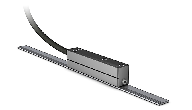
The accuracy and resolution of inductive-based motor feedback are comparable to those of magnetic systems.
One key advantage of inductive systems is insensitivity to external magnetic fields. Inductive systems are slightly more expensive than magnetic offerings, mostly because inductive read-head electronics are more complex. The scales have comparable prices.
Common motion applications with magnetic-based feedback
Material-handling automation: Requirements for handling automation equipment vary. Semiconductor handling might need a machine to quickly place thousands of tiny components on circuit boards with repeatability to within hundredths of a millimeter. In contrast, a collaborative robot might need to move boxes containing fully finished smartphone over several meters to feed a conveyor with accuracy to within a rather forgiving ±10 mm.
Consider the mass assembly of smartphones. Myriad components must be assembled very quickly and efficiently. Typically, the PCB circuit boards are prepopulated with subcomponents, but the separate phone components must still be joined. Here, automated machinery must position parts to within 0.1 mm. That means inductive or magnetic systems are most likely to be used — as the extremely high precision of optical systems is unnecessary here.

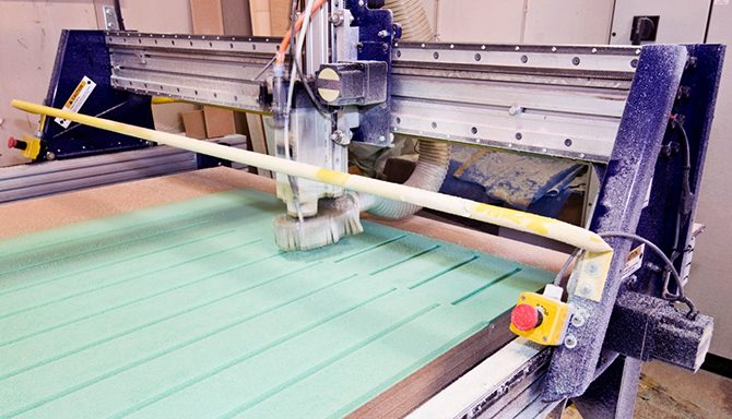
Machining: CNC-operated woodworking involves the milling of wood contours into mass-produced doors and furniture. Such operations generate sawdust that inductive and magnetic systems survive quite well.
In the same way, stone and glass working generate abrasive byproducts. But especially for window fabrication, relatively long linear motors must work quickly to efficiently transport tools between machining stations. High dynamics and fast adjustment of axes are needed — which means magnetic-based linear feedback is fairly common here.
Back in the semiconductor industry, so-called depaneling machines separate relatively large PCBs into smaller circuit boards. Usually dozens of smaller PCBs are held together by crosspieces. Snapping apart the separate boards generates a lot of dust — making magnetic measurement technology useful here too. Magnetic systems are also very compact — making them more appropriate than some inductive systems.
Robotics: Virtually all motion-feedback systems work in robotics. Various options are combined with the increasingly common variation of robot arms that encapsulates all subcomponents and uses small to medium torque motors at each joint. But the customer-specific compact design of magnetic systems is especially suitable for integration into robot systems.
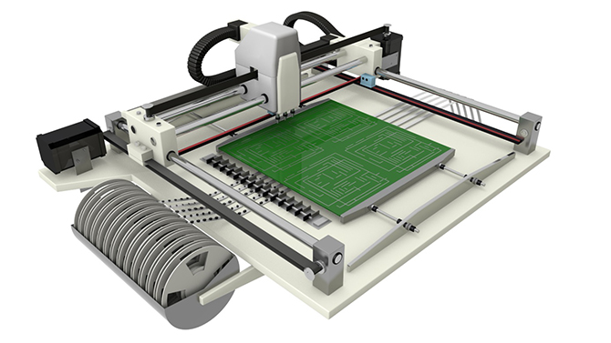
Pick-and-place applications: Precision is paramount in the automated populating of PCBs. Components including resistors, condensers, and microchips must be positioned exactly on the PCB before soldering. Optical and inductive systems are predominantly used for this purpose. But magnetic measurement technology can also be used if there’s low packing density and the design needs to be cost effective. Although the components used for populating PCBs are tiny and need precise guidance and positioning by the pick-and-place machine, magnetic sensors on some axes may be sufficient depending on the requirements for precision.
PCB working in the semiconductor industry: Optical sensors are also used in semiconductor production and inspection machines. For instance, chips are often bonded with gold or aluminum wires in cleanrooms. On integrated circuits, electronic component connections are made approximately 1 µm into the board surface … so making these connections requires absolute precision leveraging the use of optical sensors — which are 100% free from hysteresis.

Analytical and medical technology: Precision is a top design requirement for medical and analytical equipment. Patient-positioning benches for computer tomography (CT) imaging can use magnetic-based measurement technology on axes for adjusting height, inclination, and position. The tube of the CT — a large torque motor with a hollow shaft having an 800-mm or larger diameter — can also use a magnetic sensor. Absolute accuracy plays a minor role here; fast reproducibility and high repeatability matter due to the high dynamics when scanning the patient.

But analytical technologies demand even higher repeatability. Here, magnetic systems work on some axes for liquid handling: Pipetting robots quickly grasp, transport, and dispense liquid vials from sample storage vessels in very accurate and small quantities. Accurate travel between stations is vital, as the individual samples are so close together.
SIKO Products Inc. | www.siko-global.com/en-us
| Optical measurement | Magnetic measurement | Capacitive measurement | Inductive measurement | |
| Absolute accuracy | High system accuracy to ± 2 µm and better | System accuracy to ± 8 µm | System accuracy max. ± 25 µm | High system accuracy
± 3 µm |
| Repeatability | Very high repeatability | Repeatability to ±1 µm | Repeatability to 1 µm | Very high repeatability |
| Resolution | Very high resolution to 0.2 µm and finer | Moderate resolution to 0.1 µm | Very high resolution to 0.02 µm | Very high resolution to 0.25 µm and finer |
| Mechanical impact • Shock and vibration | Sensitive | Robust | Relatively robust | Robust |
| Environmental and process considerations | Sensitive to dust, shavings, oils, and fats — as well as temperature fluctuation and high humidity | Stable under external influences | Very sensitive to humidity | Stable under external influences |
| Magnetic influences | Insensitive | Sensitive (keep a safe distance) | Insensitive | Insensitive |
| Cost | Relatively expensive, highly precise solution | Similar price level as capacitive measurement systems | Saving owing to lower material cost | More expensive than magnetic measurement systems regarding the electronic system |


Leave a Reply
You must be logged in to post a comment.