
Moment of inertia is an important parameter when sizing and selecting a linear system. But it’s critical to know which type of inertia—planar moment of inertia or mass moment of inertia—is given and how it affects the performance of the system.
Planar moment of inertia
Planar moment of inertia (also referred to as second moment of area, or area moment of inertia) defines how an area’s points are distributed with regard to a reference axis (typically the central axis) and, therefore, its resistance to bending. Terminology varies, and sometimes overlaps, for planar moment and mass moment of inertia. If it’s unclear which type of moment is specified, just look at the units of the term. Planar moment of inertia is expressed as length to the fourth power (ft4, m4).
I = ∫∫ x2 dA
I = planar moment of inertia
x = distance to reference axis
dA = element of area
Second moment of area can be either planar or polar. Polar moment of inertia describes an object’s resistance to torque, or torsion, and is used only for cylindrical objects. The equation for polar moment of inertia is essentially the same as that of planar moment of inertia, but the distance used is distance to an axis parallel to the area’s cross-section.
I = ∫∫ r2 dA
I = polar moment of inertia
r = distance to reference axis
dA = element of area
The planar moment of inertia of a beam cross-section is an important factor in beam deflection calculations, and it is also used to calculate the stress caused by a moment on the beam. In linear systems, beam deflection models are used to determine the deflection of cantilevered axes in multi-axis systems. Unsupported shafts are also analyzed using beam deflection calculations.
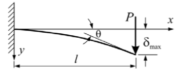
![]()
P = load
l = length of beam (distance to load)
E = modulus of elasticity
I = planar moment of inertia
Mass moment of inertia
Mass moment of inertia (also referred to as second moment of mass, angular mass, or rotational inertia) specifies the torque needed to produce a desired angular acceleration about a rotational axis and depends on the distribution of the object’s mass (i.e. its shape) around the axis. It has the same relationship to angular acceleration that mass has to linear acceleration. Mass moment of inertia, like planar moment, is typically denoted “I,” but unlike planar moment, the units for mass moment of inertia are mass-distance squared (slug-ft2, kgm2).
The mass moment of inertia equation for a point mass is simply:
I = mr2
I = mass moment of inertia
m = point mass
r = distance to axis of rotation
For a rigid body, the mass moment of inertia is calculated by integrating the mass moment of each element of the body’s mass:
I = ∫ r2 dm
I = mass moment of inertia
dm = element of mass
r = distance to axis of rotation
When sizing linear systems, the most important use for mass moment of inertia is probably in motor selection, where the ratio between the load inertia and the motor inertia is a critical performance factor.
Feature image credit: wikipedia.org

Leave a Reply
You must be logged in to post a comment.