
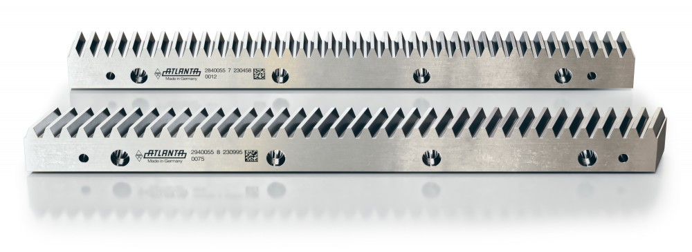
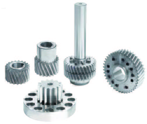
Rack and pinion systems are excellent electromechanical devices uniquely suited for achieving a linear or rotary motion solution mostly unattainable with other technologies. The typical system is made up of long straight rack (or linear gear) with teeth on one surface, a matching pinion (or circular gear), and a method for driving one or the other. Curved racks are also possible, but not as prevalent.
By Chris Popp • Motion Control Consultant
You’ve likely heard of rack and pinion steering in an automotive application. That is a slightly different animal from the focus of this article — rack and pinion sets in industrial applications. In that regard, the four main advantages of rack and pinion systems as industrial or automation solutions are:
1. High linear speeds
2. Virtually unlimited lengths of travel
3. High force transmission in a relatively compact package, and
4. A wide range of accuracy options from very high precision to general purpose use.
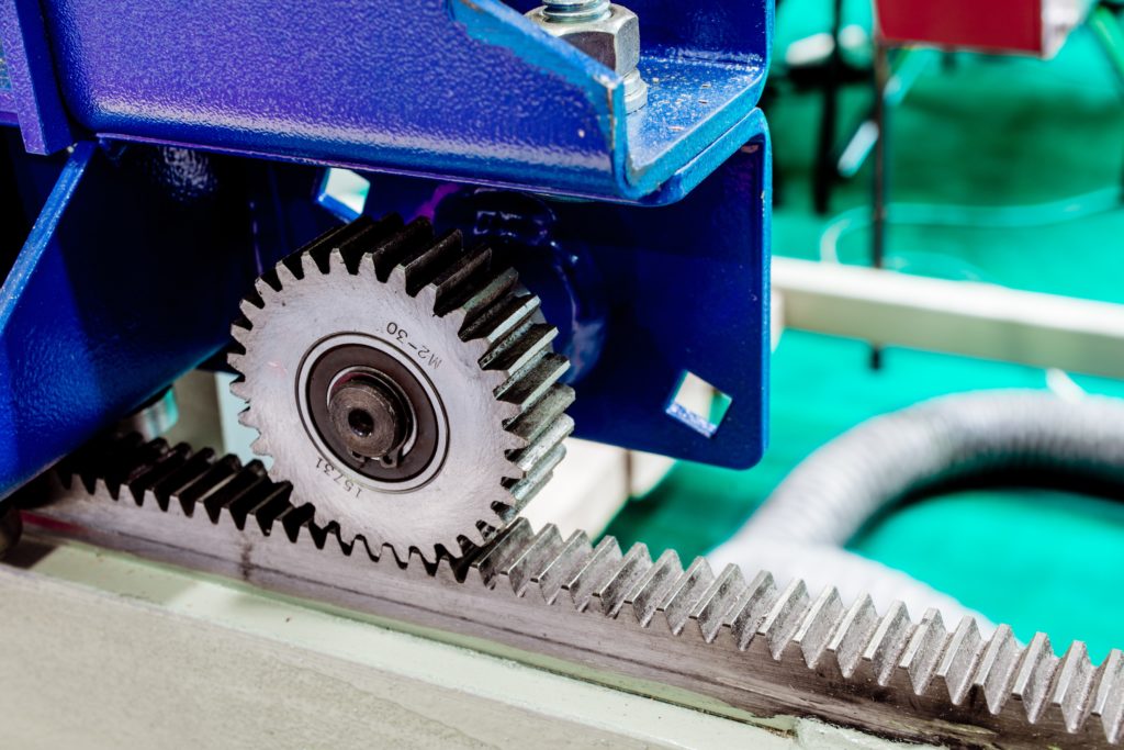
A rack and pinion system can be used in three basic ways. The first and most common is fixing the rack to the machine structure and using the reaction force on the driven pinion to move a carriage or other platform over the length of the rack — bringing the pinion and driver along with it in high-speed linear motion.
The second way to use a rack and pinion system is to fix the power/torque source, with pinion attached, which then drives the rack back and forth to create high force linear motion, like a linear actuator.
The third way is a reversal of that action by driving the rack back and forth with another linear device to create rotary motion on the pinion.
So, with the basic intro aside, let’s get to the top ten things design engineers need to consider (or in other words, what their suppliers needs to know) to correctly select and apply a rack and pinion system. Some of these may be more appropriate for the fixed-rack design, but all have relevance.

Rack and pinion parameter one: Machine drive type
This relates to whether the motion design is driving the load with a single axis on one side or with two axes on opposite sides of the load. Then, there is also the option of driving with two axes on the same side using a single rack. Identifying the power source configuration and locations will help determine torque required to drive the load, either all on one axis or shared when using multiple axes.

Rack and pinion parameter two: Operation environment
It’s important to identify the environment and ambient condition the rack and pinion will operate in to determine if any protective measures or other considerations may be required. Since the inherent design is an open gear system, any contaminants that can collect in the gear teeth should be accounted for and avoided if possible.
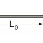
Rack and pinion parameter three: Axis travel length
As previously stated, one of the main advantages of rack and pinion is virtually unlimited travel length. Some can be longer than 200 ft … but they also work over just a foot or two — especially when using them for the alternative ways initially identified. Virtually unlimited travel means that rack and pinion sets are only limited by the builder’s ability to mount and align the rack and accompanying guides. Using longer rack pieces, many offered up to 2 m long, reduces mounting time and provides more accuracy and easier alignment over long stretches. For shorter runs, standard 1-m, 0.5-m, and custom-cut lengths are also readily available.
Rack and pinion parameter four: Axis weight being moved
In fixed-rack systems, it’s common for a carriage or gantry to move along the rack carrying a load along with it. Both the structural weight and the load weight, if combined, need to be identified to calculate the torque required to move the load. When the load varies, the worst-case scenario is the prime consideration. In a fixed pinion system, the linear force required of the moving rack, whether over the full travel or only at the end of the stroke, is similarly necessary. In either case, if any additional load or force is applied (whether during the movement or when in position) that’s a need-to-know element as well.
Rack and pinion parameter five: Axis orientation
It’s important to communicate if the movement is horizontal, vertical, or somewhere in between. In a non-horizontal application, the additional forces due to gravity will have to be considered. In horizontal applications, friction forces are a necessary added factor. Whether the tooth connection is on the top, bottom, or side of the mounted rack is also a relevant consideration in some circumstances. Not always, but it should be mentioned when discussing the proposed design configuration.
Rack and pinion parameter six: Load support
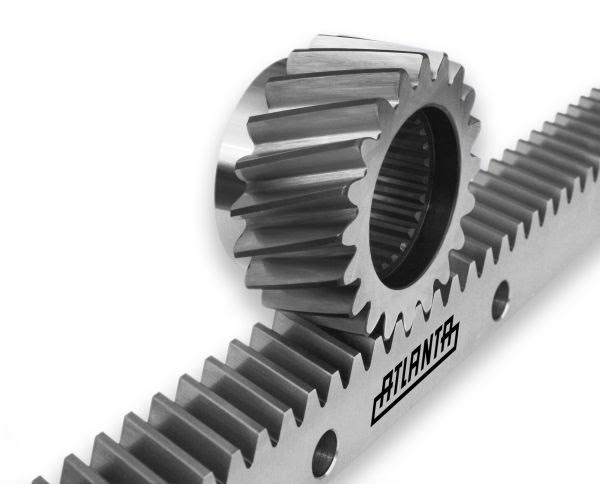
It should be no surprise that the load must be supported. How it’s supported can be critical. When using a helical cut rack side forces up to one third of the linear force can be seen. The guide system must be able to accommodate that. Therefore, linear guides should be specified to not only carry the weight of the load but also resist the side forces from the gear connection reaction. When using a straight tooth rack there are no side forces. That may allow other guide systems, like rollers, to be acceptable. Helical cut rack has some advantages, like higher force capacity and quieter operation. So, consider the application requirements before choosing the rack type. And after choosing the guide type for the rack selected, communicate the guide friction factor. That will be necessary to calculate the needed drive torque.

Rack and pinion parameter seven: Acceleration and speed
Moving the load is what it’s all about. How fast and for how long are the big questions. Like all motion applications faster inertia acceleration and deceleration requires more torque, which may lead to a larger system. Slower acceleration rates, although requiring less torque, may then need a faster run speed to get into position in time. Optimizing the motion profile for acceleration rate and run speed can reduce input drive size and costs. One of the highlighted main advantages of rack and pinion is it covers distance quickly. That offers a lot of flexibility in configuring the motion profile.

Rack and pinion parameter eight: Axis duty cycle
This is the number of operations or movements of the system, typically in cycles per hour and hours per day. While certainly a consideration for applying a relevant service factor in rack and pinion size selection, it’s much more important for the lubrication interval and the drive package, especially when a gearhead is involved. All rack selections assume proper lubrication. In applications where the pinion moves and sits for long periods of time, periodic hand lubrication may be adequate. But as the cycle increases so does the required frequency of applying lubrication.
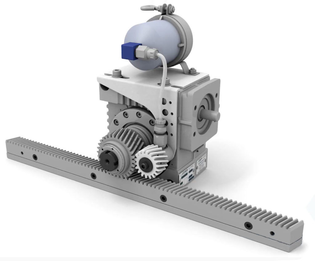
Refillable automatic “smart” lubrication systems are readily available to meter grease at appropriate quantities and intervals for each application. Gearhead life is more sensitive to starting and stopping torque. Cycles are a key factor in their selection.
Rack and pinion parameter nine: Position accuracy
This relates to the necessary positional accuracy or allowable deviation at various points along the length of travel. Taking the drive system out of the picture, this is primarily affected by the pitch error of the rack and pinion teeth. Higher tooth pitch error will result in less predictable position control. Lower pitch error will increase predictability. Many rack manufacturers offer different levels of pitch error through different hardening and grinding processes. Costs can rise dramatically from the lowest to highest quality. Therefore, it makes economic sense to identify the accuracy level really required.
A corollary element is system backlash. Clearance in the rack and pinion tooth mesh or the input gear drive system can affect position control unless the load is always in one direction. However, most rack and pinion system reversals result in some lost motion on the return. Lower rack tooth pitch error may allow closer gear mesh to reduce the effects of backlash.
Rack and pinion parameter ten: The input drive system
This involves how the rack and pinion will be driven. In most automation systems a servo motor will be selected because of its controllability. To increase mechanical advantage and reduce reflected load inertia back to the motor a gearhead of some sort is typically added. This could be a planetary inline design or a right angle servo worm. Each has its advantages. In either case, selecting an appropriate gear ratio can have a significant effect on motor and drive costs and performance. Too high a gearhead ratio will slow down the system. Too low a ratio will require a larger and pricier motor and drive.
Another consideration is pinion size. Smaller pinions must run faster to achieve desired linear speed, but require less torque to provide a given force, while also reducing the effects of backlash. A larger pinion covers more distance per revolution but requires more torque to provide the same force. Therefore, properly matching motor and drive size, gear ratio, and pinion size can optimize the system performance in the most cost effective manner.
There are certainly applications where other design criteria are important. But for most linear motion systems incorporating rack and pinion sets, identifying the ten considerations described in this article will get you 90% of the way to designing a successful and high-performing system. Because all motion system profiles are unique, it makes sense to collaborate with your system provider by sharing as much application and design information as possible. They’ve pretty much seen it all and can quickly identify the critical elements to help select the best system components to meet your needs.
For more information, visit atlantadrives.com.


Leave a Reply
You must be logged in to post a comment.