
There are many ways to build linear systems for motion in the X, Y, and/or Z directions – also known as Cartesian coordinates. The terms we generally use to refer to these systems depend on how the axes are assembled, where the load is positioned, and to some extent, what type of use the system was designed for. In many industrial applications, Cartesian and gantry-style robots are prevalent, but in precision applications, XY tables are often the better choice, due to their compact, rigid structure and very high travel and positioning accuracies.
Cartesian systems
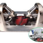
Cartesian systems consist of two or three axes: X-Y, X-Z, or X-Y-Z. They often incorporate an end effector with a rotational component for orienting the load or workpiece, but they always provide linear motion in at least two of the three Cartesian coordinates.
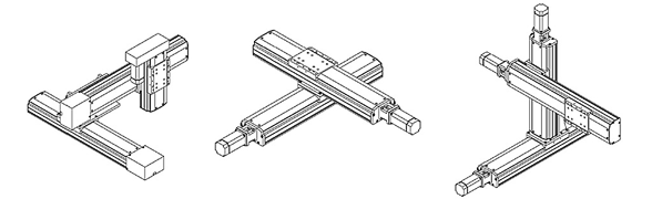
Image credit: Servo Vision Co., Ltd
When a Cartesian system is used, the load is usually cantilevered from the outermost axis (Y or Z). For example, in an X-Y gantry, the load is mounted to the Y axis, either to the end of the axis or at a distance from the axis, creating a moment arm on the Y axis. This can limit their load capacity, particularly when the outermost axis has a very long stroke, creating a large moment on the lower, supporting axes.
Cartesian systems are used in a wide range of applications with maximum strokes on each axis typically one meter or less. The most common of these applications include pick-and-place, dispensing, and assembly.
Gantry systems
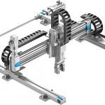
To address the issue of outer axes causing a moment load on the inner axes, gantry systems use two X axes, and in some cases, two Y and two Z axes. (Gantries almost always have three axes: X, Y and Z.) The load on a gantry system is located within the gantry’s footprint and the gantry is mounted over the working area. However, for parts that cannot be handled from above, gantries can be configured to work from below.
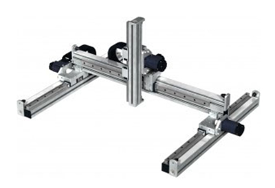
Image credit: Northwest Motion
Gantry systems are used in applications with long strokes (greater than one meter) and can transport very heavy payloads that are not suitable for a cantilevered design. One of the most common uses for gantry systems is overhead transport, such as moving large automotive components from one station to another in an assembly operation.
XY tables
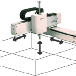
XY tables are similar to XY Cartesian systems, in that they have two axes (X and Y, as their name implies) mounted on top of each other, and typically have strokes of one meter or less. But the key difference between XY Cartesian systems and XY tables lies in how the load is positioned. Instead of being cantilevered, as in a Cartesian system, the load on an XY table is almost always centered on the Y axis, with no significant moment created on the Y axis by the load.
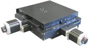
Image credit: Dover Motion
This is where the principle of “how the system is used” helps distinguish between the various types of multi-axis systems. XY tables generally work only within their own footprint, meaning the load does not extend beyond the Y axis. This makes them best suited for applications where a load needs to be positioned in the horizontal plane (X-Y). A typical example is a semiconductor wafer being positioned for inspection, or a part being positioned for a machining operation to take place. Designs referred to as “open-frame” or “open aperture” have a clear opening through the center of the table. This allows them to be used in applications where light or objects need to pass through, such as back-lit inspection applications and insertion processes.
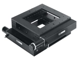
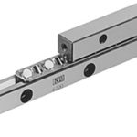
Image credit: Parker Hannifin Corporation
Because XY tables are primarily used for very high precision applications, the guideway of choice is crossed roller slides, which provide extremely smooth and flat travel. Drive mechanisms are typically ball screw or linear motor, although very fine pitch lead screws are also common.

Great writeup. What is this type of linear system is this called?
https://drive.google.com/file/d/1hH6J2r_lf9sRNnW8qPkX8hYzRNWulobr/view?usp=sharing
I’m trying to build one for a musical device. Manual adjustment knobs should be on the same side. Overall dimension is small 100mm x and y travel With the knobs its 150mm long. Anything out there that will allow me to build a prototype?
Look forward to hearing a solution. as I don’t think
Joe