
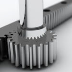
Rack and pinion drives are often used in applications that require stroke lengths beyond the practical limits of ball screws and thrust forces that exceed the capabilities of belt drives. And in some applications, rack and pinion systems can also provide lower total inertia than a suitable ball screw or belt drive alternative, which can reduce the overall mass, footprint, and cost of the system while improving positioning accuracy in dynamic applications.
There are two common ways that a rack and pinion system can be used: by making the rack stationary and driving the pinion along the length of the rack, or by making the pinion stationary and using it to translate the rack back-and-forth.
In this example, we demonstrate how to calculate the total inertia for a rack and pinion system configured with the rack stationary and the pinion moving, since this is the arrangement used most often in linear actuators, gantry systems, and other linear motion applications.
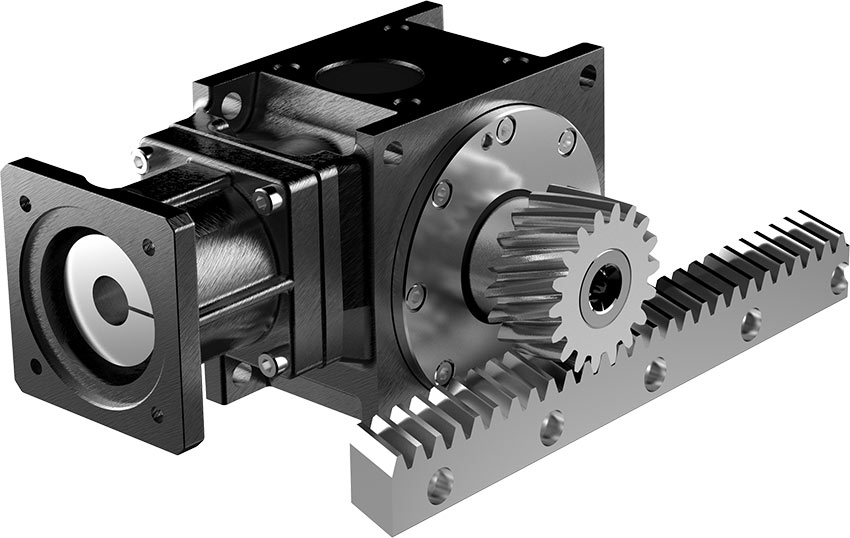
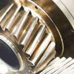
Image credit: Nidec Corporation
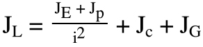
In a typical rack and pinion system, the moving components that make up the total load inertia are the applied load, the pinion, the coupling, and the gearbox (if included in the system).
![]()
JL = total load inertia reflected to the motor (kgm2)
JE = inertia of applied load (kgm2)
Jp = inertia of pinion (kgm2)
Jc = inertia of coupling (kgm2)
JG = inertia of gearbox (kgm2)
The load can be considered as a point mass rotating about the pinion. Keep in mind that the load will likely be mounted to the pinion by a carriage or a table, so the mass in this equation should include the mass of the applied load and the mass of the mounting table or carriage.
![]()
JE = inertia of applied load (kgm2)
m = mass of applied load, including mounting table or carriage (kg)
r = radius of pinion (m)
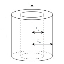
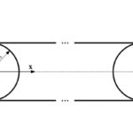
The inertias of the pinion and the coupling are typically provided by their manufacturers, but if they need to be calculated, they can be modeled as hollow cylinders (Jph), since they both have hollow bores.
![]()
Jph = inertia of hollow cylinder (pinion or coupling) (kgm2)
m = mass of cylinder (kg)
ro = outer radius of cylinder (m)
ri = inner radius of cylinder (m)
Like belt drive systems, rack and pinion systems often incorporate a gearbox, so the total inertia reflected to the motor includes the effect of the gear ratio and the added inertia of the gearbox.
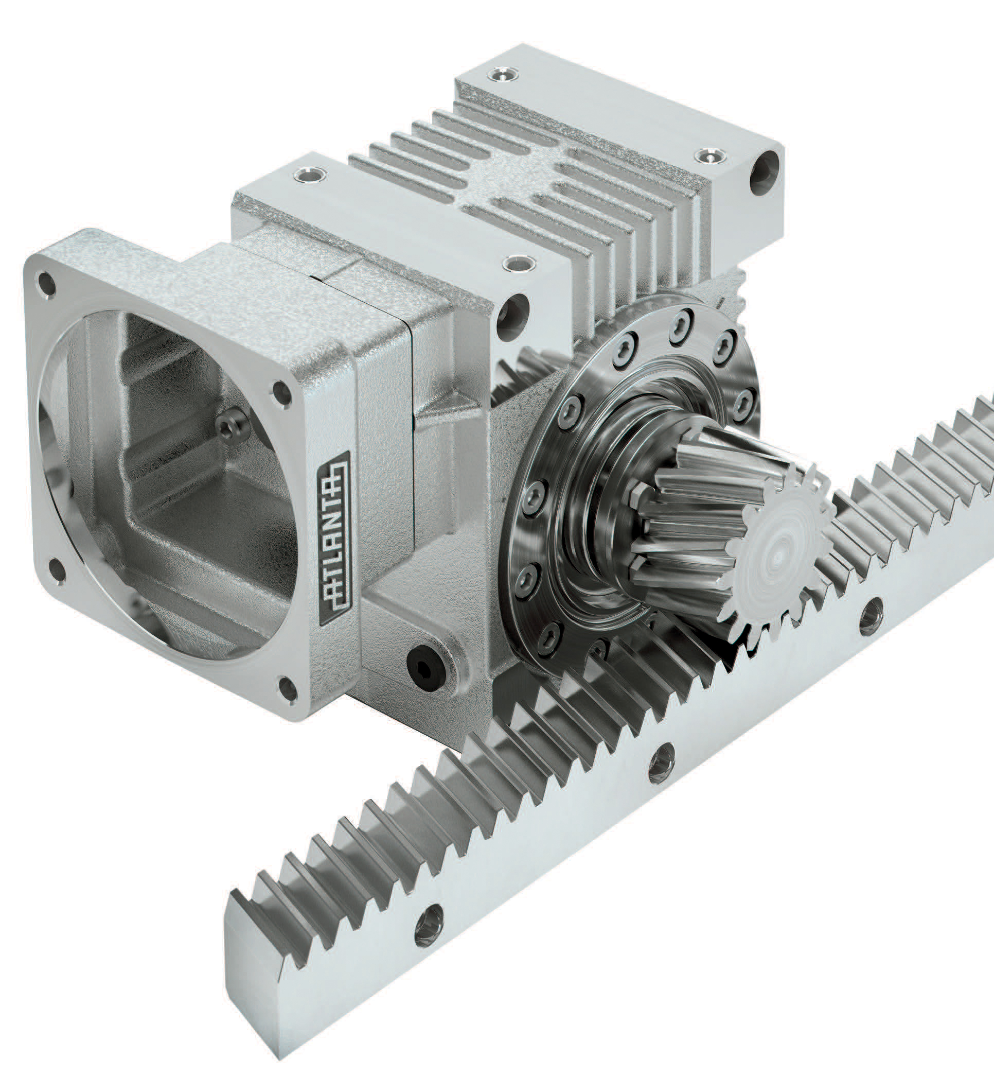 In most rack and pinion systems, the gearbox output shaft mounts directly into the bore of the pinion, so no coupling is needed between the gearbox and the pinion.
Depending on the input configuration of the gearbox, there may or may not be a coupling between the motor and gearbox. If the gearbox has a hollow bore input that matches the size of the motor shaft, no coupling will be needed. But if the gearbox has a shaft on the input side, or if the motor shaft doesn’t match the gearbox input bore, then a coupling will be needed.
If a coupling is used to connect the motor to the gearbox, keep in mind that because of its location (before the gearbox), the coupling won’t be affected by the gear ratio, so its inertia is added after the gear ratio is applied, along with the gearbox inertia.
JL = total load inertia reflected to the motor (kgm2)
JE = inertia of applied load (kgm2)
Jp = inertia of pinion (kgm2)
i = gear ratio
Jc = inertia of coupling (kgm2)
JG = inertia of gearbox (kgm2)


Leave a Reply
You must be logged in to post a comment.