
Inertia matching is one of the inexact sciences of motion system design. When a motor and a load are coupled together, the ratio of load inertia to motor inertia determines how well the motor can control the load during acceleration and deceleration. In theory, a “perfect” inertia match of 1:1 (load inertia equals motor inertia) should be the goal, but in the real world, this may not be achievable or practical.
Inertia is best described as an object’s resistance to change in speed and is related to the object’s mass and distance from the axis of rotation. The classic example of inertia is a figure skater spinning on the ice. With her arms outstretched, she spins at a relatively slow speed, because a portion of the spinning mass (her arms) is far from the axis of rotation (her standing leg), giving her a large inertia. When she brings her arms in toward her body, all of the spinning mass is now closer to the axis of rotation, which reduces her inertia and increases her rate of spin.
Load versus Motor Inertia
If electromechanical systems were rigidly coupled, with no compliance or “wind-up” in the system, performance would be determined by the motor torque, and inertia would be irrelevant. But since mechanical components aren’t infinitely rigid – belts stretch, gears have backlash, and couplings are elastic – designers must decide what inertia ratio is acceptable for each specific application.
![]()
JL = inertia of load reflected to motor
JM = inertia of motor
![]()
JD = inertia of drive (screw, belt & pulley, or actuator)
JE = inertia of external (moved) mass
JC = inertia of coupling
A common rule of thumb is to strive for an inertia ratio of 10:1 or less. A higher ratio increases system response time and resonance, causing the system to overshoot the target velocity and position. Large inertia mismatches also require the motor to draw more current, making the system less efficient and more costly.
High precision feedback mechanisms can be implemented to monitor both position and velocity, and servo controllers can be tuned to improve the motor’s ability to control the load, but the best system stability is achieved with mechanical solutions. If the inertia ratio is too high and the desired performance cannot be achieved via feedback measuring and servo tuning, there are two mechanical options to decrease the inertia ratio – adding a gearbox or using a larger motor.
Gear Ratio and Inertia
The addition of a gearbox to the system can decrease the inertia ratio significantly, since the gear reduction has an inverse square effect on the load inertia.
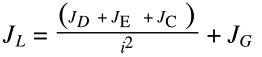
JG = inertia of gearbox
i = gear ratio
Belt driven systems often use a gearbox to optimize the motor torque and speed, and in these cases, decreasing the inertia ratio via gear reduction is a no-brainer. But adding a gearbox to a system solely for the purpose of reducing the load inertia is not always the best solution. Gearboxes add inefficiency and further compliance to the system. They also increase cost both in terms of added components and additional energy consumption.
Motor Size and Inertia
Another way to reduce the inertia ratio is to use a larger motor with a higher inertia. However, like the addition of a gearbox, this can be a costly remedy, as a larger motor is typically more expensive and consumes more energy. A motor with higher inertia also uses more of its available torque to overcome its own inertia, making it less efficient.
Back to the “rule of thumb” regarding the inertia ratio. It is true that the more compliant the system, the lower the inertia ratio should be in order for the motor to effectively control the load and minimize overshooting. And systems that require high acceleration and deceleration or extremely precise positioning require a low inertia ratio in order to achieve the desired performance. But for most electromechanical applications, striving for a “perfect” inertia ratio of 1:1 can mean oversized components, higher system cost, and more energy consumption.

Where you have written “Inertia”, you should have save “Rotational Inertia” or “Moment of Inertia”. “Inertia” on it’s own refers to an objects “Linear Inertia”.
As you know, an objects inertia does not change if only the distribution of mass changes. But you said that when a figure skater brings her arms in towards her body (i.e. reduces the distribution of her mass), her inertia reduces. This is wrong. What you meant to say is that her rotational inertia reduces.
Danielle,
Thank you so much for your explanation. It’s the best one I’ve found on the internet.
Cheers,
Le
What about having too low of a ratio? For instance a ratio of 0.75?
Having a “too low” Inertia mismatch ratio is a good thing, if you haven’t had to pay for it. I think of lower than 1:1 being a negative mismatch, and an unfortunate double negative! A negative mismatch is a match, right? So, maybe a fortunate concept in that there is no limit to how negative you’d like it to be.
Let’s say you know you must have a gearhead for whatever reason, torque requirements, or just to get your inertia mismatch under 10 to 1.
Remember that the reflected inertia of the payload is divided by the square of the reduction ratio.
What you should be shooting for is some margin on the speed you need to go with your bus voltage and winding, referring to the motor’s torque-speed curve, so maximise the reduction ratio as much as you can. There’s a little cost difference between a gearhead of 10:1 or 20:1, and that inverse square bit makes the payload seem 4x less than the 10:1 with the 20:1 gearhead .
The why of it is that your payload can change greatly without having to revisit the tuning, which is important for heavy pick and place, or when applying widely varying forcing functions in some process.
Mike
Thanks Mike – a very good explanation of why, if you’re already adding a gearbox to an application, you should maximize the gear ratio (and the resulting inertia match) as much as possible, given the application requirements and your motor’s torque-speed curve.