
Belts and rack and pinions have several common benefits for linear motion applications. They’re both well-established drive mechanisms in linear actuators, providing high-speed travel over extremely long lengths. And both are frequently used in large gantry systems for material handling, machining, welding and assembly, especially in the automotive, machine tool, and packaging industries.
Timing belts for linear actuators are typically made of polyurethane reinforced with internal steel or Kevlar cords. The most common tooth geometry for belts in linear actuators is the AT profile, which has a large tooth width that provides high resistance against shear forces. On the driven end of the actuator (where the motor is attached) a precision-machined toothed pulley engages with the belt, while on the non-driven end, a flat pulley simply provides guidance. The non-driven, or idler, pulley is often used for tensioning the belt, although some designs provide tensioning mechanisms on the carriage. The type of belt, tooth profile, and applied tension force all determine the force that can be transmitted.
Image credit: Brecoflex Co., L.L.C
Rack and pinion systems used in linear actuators consist of a rack (also referred to as the “linear gear”), a pinion (or “circular gear”), and a gearbox. The gearbox helps to optimize the speed of the servo motor and the inertia match of the system. The teeth of a rack and pinion drive can be straight or helical, although helical teeth are often used due to their higher load capacity and quieter operation. For rack and pinion systems, the maximum force that can be transmitted is largely determined by the tooth pitch and the size of the pinion.

Image credit: MultiCam Canada
Despite their overlap in capabilities and uses, there are some performance criteria that can steer the decision between belts and rack and pinion systems. Below are the application parameters that can have the most influence on which technology to use.
Stroke length
Both belts and rack and pinions can accommodate very long travel lengths. Case in point: belt drive actuators have been built at lengths up to 14 m. But, after a point, tensioning the belt becomes problematic. This is because the longer the belt, the higher the required tension force and the farther the tensioning mechanism (such as the idler pulley) needs to travel to “pull” the belt into tension. In theory, a belt could be almost infinitely long, but in reality, there’s a practical limit to how far the tensioning mechanism can travel. In addition, as more tension force is induced on the belt, the external force it can transmit decreases. Longer belts also add to the moved mass and inertia, which can drive the need for a larger motor.
Rack and pinions, on the other hand, can be constructed in nearly unlimited lengths. Rack sections can be joined endlessly, although the guide mechanism (profiled rail or cam roller, for example) can be the limiting factor in maximum stroke length. Rack and pinion systems can operate in one of two ways: with the pinion (including gearbox and motor) moving and the rack stationary, or with the pinion assembly stationary and the rack moving. The first scenario is more common, although it does introduce more complex cable management. The benefit of a moving pinion assembly is that the moving mass and inertia are lower than if the entire rack were the moving component. This keeps the required motor smaller and eliminates the need for extremely high gear ratios.
Positioning accuracy
While rack and pinion systems have not historically been thought of as “precise” when compared to ball screws and linear motors (although that perception is changing), they do hold an advantage over belt drives in terms of positioning accuracy. This is because no matter how precise the belt profile and pulley teeth are, it’s an unavoidable fact that belts have compliance and are plastic. This means that they will eventually stretch, especially if their tensile strength is exceeded.
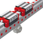
Rack and pinion systems do have backlash, due to the meshing of gear teeth. But high precision helical rack and pinion systems have tooth pitch errors in the single-micron range. It’s also possible to preload a rack and pinion system to prevent backlash. This is done with either a split-pinion or a dual-pinion design. In the split-pinion design, two pinion halves mesh with opposite tooth flanks on the same rack. One pinion half is driven and the other half is preloaded with an axial spring pack in order to remove backlash. The dual-pinion design uses a driven (aka “master”) pinion and a preloaded (aka “slave”) pinion, each driven by a gearbox and motor. Preload is managed electronically through the controller.
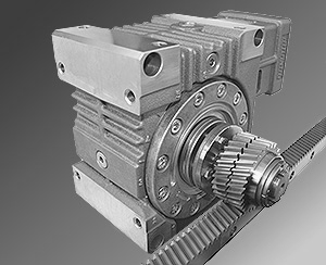
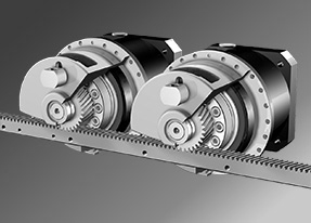
Image credit: ATLANTA Drive Systems, Inc.
Vertical applications
Manufacturers regularly discourage the use of belt driven actuators in vertical applications, due to the risk of damage—or more importantly, personal injury—if the belt breaks or the brake mechanism fails. While rack and pinion systems can be back driven like ball screws, they are much less likely to experience catastrophic failure in vertical applications.
Harsh environments
Here, belt driven actuators generally have the advantage, since belts are relatively unaffected by liquid contamination such as water or oil. (Caustic liquids can, however, degrade belt material.) And most belt driven actuators can be sealed to avoid the ingress of contamination.
Rack and pinion actuators, on the other hand, are open systems, with no simple and effective way to enclose them. But mounting a rack and pinion system on its side or upside down can minimize the amount of debris that makes its way onto the rack.
Maintenance
While belt and pulley systems do not require lubrication, the metal-on-metal contact of rack and pinion systems, together with the tight clearances between gear teeth, make lubrication critical. Automatic lubrication systems are recommended for use with rack and pinions to ensure proper lubrication at all times and avoid reduced performance or even failure. Keep in mind, however, that regardless of the drive type—belt or rack and pinion—the guide mechanism used in the actuator will most likely require lubrication.
Feature image credit: Wittenstein alpha GmbH


Leave a Reply
You must be logged in to post a comment.