
When selecting linear guides, have you ever seen a disclaimer in the catalog or on the manufacturer’s website regarding dynamic load capacities? It typically reads something like this:
Dynamic load capacities are based on 100,000 m of travel. When comparing to products for which load capacities are based on 50,000 m of travel, multiply the 100,000 m rating by 1.26.
If you saw this, you probably wondered where the 1.26 comes from and why it’s important. To find out, we’ll look at the bearing life equations for each rating to derive the conversion factor. But first, let’s review the difference between static and dynamic load capacity.
Static load capacity, according to ISO 14728 Part 2 regarding rolling bearings, is the force that causes permanent deformation of the rolling element (ball) and raceway, which equals 0.0001 times the rolling element diameter. This is an important specification because if it is exceeded, the running characteristics of the bearing will be compromised. However, the static load capacity is only valid when the bearing is in a non-moving state. So while it’s critical to consider the static load capacity in your linear bearing selection, it is the dynamic load capacity which is used for calculating bearing life.
Dynamic load capacity is the load at which a linear guide will, with 90% certainty, achieve the targeted service life before fatigue (flaking) occurs on the rolling elements or raceways. The ISO 14728 Part 1 specification allows either 50,000 m or 100,000 m to be used as the targeted service life for dynamic load capacity. Therefore, in order to make a comparison between different manufacturer’s linear guides, you need to know whether their dynamic load ratings are based on 50,000 m or 100,000 m. This is where the 1.26 conversion factor becomes important.
Equations for calculating linear-bearing life
To begin, we’ll set up the bearing life equations for 50,000 m service life and 100,000 m service life:
![]()
![]()
Setting the life equations equal to each other allows us to begin deriving the ratio of C50 to C100:
![]()
Moving the variables to one side of the equation gives us:
Which can be simplified to:

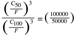
The applied force is the same for both life calculations, so F can removed from the numerator and the denominator, leaving us with:
![]()
To get rid of the third power on the left side, we’ll take the cube root of both sides:
![]() This gives us the ratio we’re looking for:
This gives us the ratio we’re looking for:
![]()
In a more practical form, the load capacity of a bearing based on 100,000 m should be multiplied by 1.26 in order to make an accurate comparison with a linear bearing for which load capacity is based on 50,000 m:
![]()
And conversely, the load capacity of a bearing based on 50,000 m should be divided by 1.26 in order to make an accurate comparison with a bearing for which load capacity is based on 100,000 m:
![]()
As an analogy, think of jogging with a backpack full of weights. If you’re jogging 10 miles, you might only be able to carry 20 lb of weights without becoming tired. But if you’re only jogging 5 miles, you can easily carry 25 lb of weights without fatigue. This same principle underlies the conversion between load capacity based on 100,000 m of life and 50,000 m of life.
By understanding the theory behind the 1.26 conversion factor and applying it when necessary, you can avoid the upfront cost of oversizing the linear bearings for your application or the long-term cost of downtime and repair due to undersizing.

How do we calculate the force ?
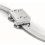
I mean, I’m using a Monorail guideway for linear motor, I am unable to calculate the equivalent dynamic force on bearing, since my load is offset to the center. I need to calculate the running life of the bearing.
Please guide in details.