
Motion controller and drive features can address the natural behavior of motion stages that can otherwise degrade throughput and accuracy — including those arising from mechanical resonances, inertia mismatch, motor cogging, backlash, friction effects, and encoder signal distortion.
By Jason Goerges and Boaz Kramer • ACS Motion Control
Precision motion stages operate in industrial applications with demanding motion requirements — in equipment for semiconductor inspection, metrology, and lithography, laser micromachining and microprocessing, and genome sequencing equipment, to name a few.
Motion controller and drive features can address stage behavior that can otherwise limit throughput and accuracy — including those associated with mechanical resonances, inertia mismatch, motor cogging, backlash, friction effects, and encoder signal distortion. Such controller and drive features optimize overall motion system performance to meet or exceed demanding application specifications. More specifically, motion controllers can improve move and settle times, standstill jitter, and velocity regulation and smoothness, which in turn boosts machine throughput and accuracy.
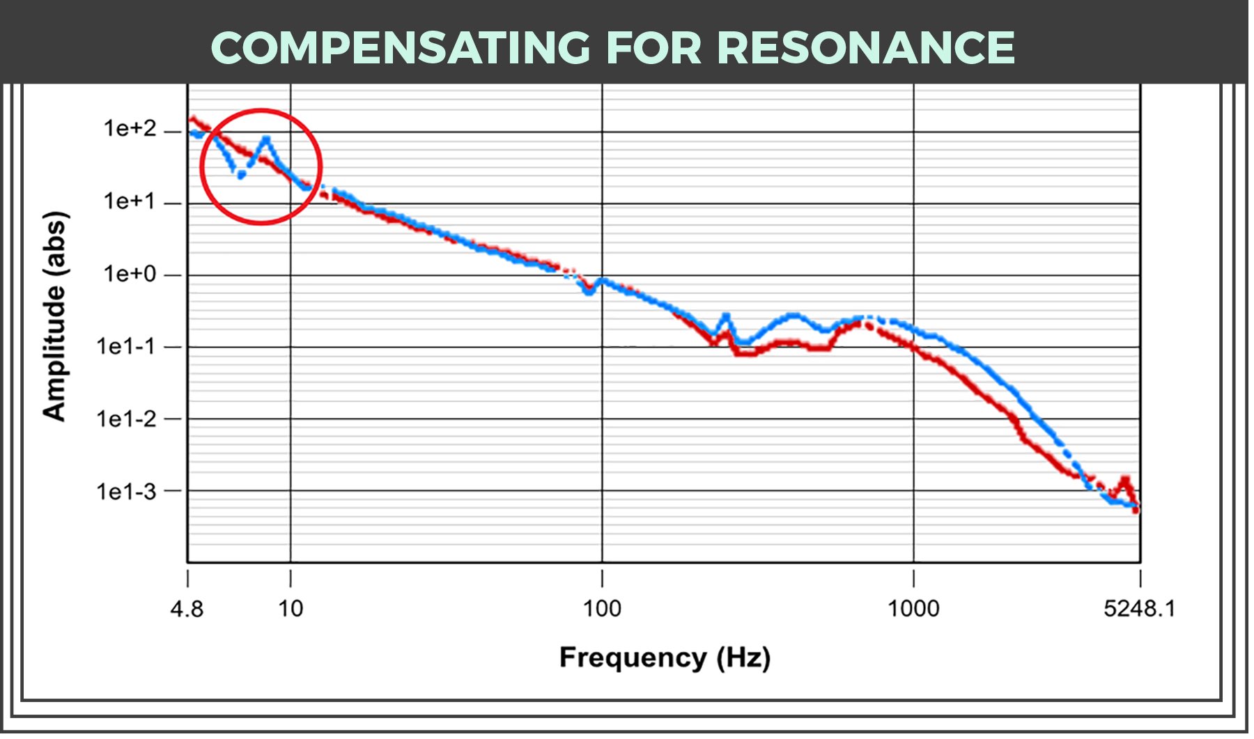
Addressing precision motion stage mechanical resonances with motion controllers and drives
Indirect-drive stages such as ballscrew stages typically exhibit distinct low and high frequency resonances, whereas direct-drive linear and rotary motor stages only exhibit high frequency resonances. For more on this topic, refer to the classic paper by George Ellis: Cures for Mechanical Resonance in Industrial Servo Systems — Contained in the Proceedings of IEEE IAS, Sep. 30 – Oct. 4, 2001.
In general, the higher the resonant frequencies, the better. The catch is that getting higher resonant frequencies typically requires more expensive stage materials and designs. A motion controller or drive with user-configurable biquad filters, acceleration feedback compensation (refer again to the Ellis paper), and adaptive control algorithms can often minimize or eliminate the effects of mechanical resonances. This in turn allows for the use of more economical stage designs.
Adaptive algorithms are particularly effective in volume production environments where the resonant frequencies may shift slightly from one stage to another because of manufacturing and assembly tolerances. Adaptive algorithms also significantly improve robustness in uncertain or changing operating environments — including on-the-fly load changes in pick and place or direct-imprint lithography applications using Ultratech Titan technology. Powerful software tools facilitate optimization of the features and algorithms.
Besides resonant frequencies of the stage and coupled load, there can be other components in the system with resonant frequencies excitable by stage motion — such as cantilevered inspection heads or the machine frame itself, for example. Oscillation due to these resonances may or may not be observable by the motor or load encoders. Useful techniques to minimize or eliminate the excitation and effect of such resonances include input or profile shaping, disturbance-rejection algorithms, accelerometer-based compensations, and more.
How to address the challenge of inertia mismatch
Depending on the motor-load coupling, inertia (mass) mismatch can make it extremely difficult to tune a servo system to stability and meet bandwidth goals. But system design constraints may make it impossible to avoid significant mismatch ratios on the order of 100:1 or even as high as 10,000:1. Traditional industrial motor-drive servo algorithms can’t properly handle such mismatch ratios. In contrast, drives with advanced servo algorithms — including cascaded loops, high-order digital filters, and adaptive tuning — are proven capable of successfully controlling stages with such mismatches … and with a high bandwidth. In other words, the axis will settle into position quickly, and that ultimately boosts overall machine throughput.
For an advanced algorithm to be generally effective, the controller or drive provider must make it simple to optimize. Abstracting complexity from the user by limiting the number of “knobs to turn” (so to speak) and providing a straightforward approach to optimize performance is generally desirable. That’s why software tools for algorithm optimization are as important as the algorithms themselves. Automatic or minimal (even single) parameter tuning tools as well as frequency-response function-analysis tools are two examples.
Compensating for iron-core motor cogging issues
Iron-core linear-motor-based stages generally suffer from motor cogging that generates inconsistent motor force during motion. That in turn typically degrades motion smoothness. This can be especially problematic for applications needing smooth constant velocity motion such as high-resolution inspection or printing.

Advanced servo algorithms can identify and compensate for cogging in iron-core motors to the extent that they can reach the same or similar performance as an ironless motor. This allows for the possibility of using iron-core motor stages in applications which would have otherwise been limited to ironless motors. Leveraging on higher torque (force) density of the iron-core motor can allow for a potential increase in achievable acceleration and throughput. Alternatively, an iron-core motor may allow for improved packaging and/or reduced footprint and cost compared with an ironless motor based stage design.
Solutions to the effects of friction
Precision motion stages employ mechanical or fluid/air bearings which are typically calibrated with a high degree of precision. Ideally, the friction within these bearings is uniform over the entire travel range (and for air bearings is effectively negligible). In reality however, friction and bearing load may change as a function of position in the range of travel, and the friction impact may even change over time and/or with environmental conditions (temperature, humidity , and so on.). Furthermore, static friction is a highly nonlinear phenomenon and is typically very difficult to characterize. Advanced controller algorithms can provide both feedforward and feedback-based compensation to minimize the effect of varying friction on the servo loops. Friction and its impact on motion performance can even be monitored over long periods of time to preemptively determine when a bearing may need maintenance or repair.
Addressing encoder signal distortion
Encoder signal fidelity can have a significant impact on achievable motion performance. Alignment or calibration inaccuracy can spur signal gain, phase, and offset distortions in the case of incremental analog SinCos encoders, whose signals are typically measured and represented with Lissajous plots. Such distortions create disturbances which spur increased following error and are detrimental to applications needing extremely smooth motion such as high resolution digital printing and wafer inspection. Some advanced motion controllers offer important software tools to measure such signal distortions, and built-in parameters and algorithms to compensate for them.

Meeting or exceeding demanding motion-system specifications: Move and settle
Perhaps the most critical spec for demanding test and measurement applications such as wafer inspection and metrology is the ‘Move and Settle’, since it has a direct correlation to machine throughput. Such an application spec may have multiple ‘move’ distance values ranging from µm to millimeters, and multiple ‘settle’ window values, ranging from nanometers to µm. Adaptive algorithms can enable the user to employ a single set of servo tuning parameters and still meet or exceed spec under all test conditions. Advanced motion profile generation techniques can also minimize the energy injected into the system by the stage motion, resulting in reduced following error and settling time.
Meeting or exceeding demanding motion-system specifications: Standstill jitter
A frequent complementary specification to move and settle is standstill jitter — the maximum allowable motion of the stage between moves … when the inspection or metrology measurement is made, for example. This can be on the order of nanometers or less for the most demanding applications. Getting such specification can be very challenging, especially for large format stages which need high power motors and drives to generate the forces (currents) necessary to meet high-throughput requirements.

In fact, traditional PWM drives may be unsuitable for such applications because (besides other nonlinearities):
- They generate a switching noise, which can degrade feedback or other system signals
- They generate a quantization noise that’s associated with the current and PWM control circuitry.
Linear drives (because of their high dynamic range and minimal noise generation) are often favored for such applications. However, they have inherent disadvantages — including poor efficiency (resulting in a larger footprint and increased heat dissipation) and more complex and expensive protection schemes. Some technologies combine the advantages of PWM and linear drives to enable nanometer or even sub-nanometer standstill jitter.
Meeting or exceeding demanding motion-system specifications: Velocity regulation and smoothness
Applications involving on-the-fly measurements may need the motion system to maintain a very high degree of velocity regulation. There are multiple ways to measure and quantify velocity regulation or smoothness. One of the simpler methods is to track following error while at speed. For example, one such a specification could be 100-nm (3-sigma) at 250 mm/sec. To meet such demanding specifications, the drive must be able to make extremely small adjustments very rapidly. In other words, the drive must have a high dynamic range.
Using an advanced proprietary PWM drive technology, it is possible to achieve a dynamic range of 200,000:1, which is well suited for such applications — especially when paired with features we described earlier in the article that address natural stage phenomena.


Leave a Reply
You must be logged in to post a comment.