
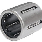
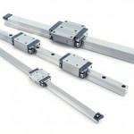
One of the fundamental steps in selecting a recirculating linear bearing, whether profiled rail or round shaft type, is to calculate the bearing life. But how is this calculation derived, and what does it mean in the “real world?”

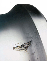
Image credit: The Barden Corporation
Bearing life for recirculating linear bearings, often referred to as the L10 life, is a method of specifying the travel that a bearing can achieve before it reaches its fatigue life, which is the occurrence of the first signs of flaking on the raceways or the rolling elements. The term “L10” is used (rather than, say, L5 or L25) because this is the distance that 90 percent of seemingly identical bearings, operating under identical conditions, can travel before fatigue occurs. In other words, the L10 life gives a 90 percent reliability that the bearing will achieve the specified travel.
The calculation of L10 life for recirculating bearings with balls as the load-carrying elements, is given by:
![]()
And for recirculating bearings with rollers as the load-carrying elements, the equation is:
![]()
Where:
L = bearing life (m)
C = bearing dynamic load capacity (N)
F = applied dynamic load (N)
Although the bearing life equation is relatively straightforward, there are some nuances to determining bearing life that users should be aware of.
First, the dynamic load capacity, C, of a recirculating linear bearing is determined by the manufacturer in accordance with ISO 14728-1. The ISO standard defines dynamic load capacity as the load—constant in magnitude and direction—at which the linear bearing (ball or roller) can provide 100 km (100,000 m) of travel before fatigue occurs.
However, some manufacturers base the dynamic load capacity of their linear recirculating bearings on a travel of 50 km (50,000 m). The ISO standard acknowledges this difference and provides a dynamic load rating conversion factor that should be used when comparing bearings rated for 50 km with bearings rated for 100 km of travel. In these cases, one of the following conversion methods should be applied:
- multiply the dynamic load capacity of the 100 km bearing by 1.26, or
- divide the dynamic load capacity of the 50 km bearing by 1.26
(To see how the 1.26 correction factor is derived, check out this article.)
Second, the ISO standard specifies that the bearing life applies to linear motion rolling bearings “with contemporary, commonly used material and manufacturing quality and under conventional operating conditions” (emphasis added). In the real world, many applications operate in conditions with high temperatures, shock loads, or other factors that will reduce bearing life, but that are not accounted for in the bearing life equation.
To adjust for these conditions, manufacturers provide factors that either de-rate the dynamic load capacity or increase the applied load, reducing the bearing life accordingly. For example, if a bearing operates under heavy impacts or vibrations, the applied load would be multiplied by a factor between 2.0 and 3.0.
Depending on the manufacturer and bearing type, correction factors may be provided for the following conditions: shock loads/vibrations, special mounting situations (such as two bearings used with minimal spacing between them), shaft hardness (when it falls below HRC58), high temperatures, and short stroke applications.
Although the standard L10 life is based on a reliability of 90 percent, it is possible to specify bearing life at a higher reliability level. In order to do this, the bearing life equation is multiplied by a factor corresponding to the desired reliability. For example, the factor for bearing life with 95 percent reliability, which is denoted L5, is 0.62. So the bearing life equation for 95 percent reliability is given as:
![]()
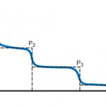
The load on a linear bearing often changes during the course of its life, or even during the course of one move cycle. In order to accurately estimate bearing life under changing load conditions, the mean equivalent dynamic load, Fm, is used.
In the ideal world, a bearing would be selected by testing it under actual load conditions, but in the real world, this is almost never practical. Although bearing life calculations are statistical predictions, and there are many factors that affect a bearing’s actual service life, the dynamic load capacity ratings and life calculations provided by ISO 14728-1 are well-proven and accepted across the linear bearing industry.
Feature image credit: Thomson Industries


Leave a Reply
You must be logged in to post a comment.