
Most linear guide and screw manufacturers offer online tools to help engineers with product sizing and selection. But these tools can sometimes be more in-depth – or alternatively, more simplified – than is needed at the current design or selection phase. In these cases, the easiest and fastest solution is to do the sizing yourself. (And if you’re really old-school, that involves a quad-rule engineering pad and a mechanical pencil!)
If you’re the type who prefers to do product sizing and selection yourself, or, if you just want to understand the calculations behind manufacturers’ sizing programs, you’re in luck. Here, we’ve compiled 12 sizing resources for linear guides and screws covering a wide range of application scenarios.
L10 bearing life
A bearing’s L10 life is the travel it can achieve before reaching its fatigue life. This tutorial explains how the fatigue life is determined and how to calculate the L10 bearing life.
Static load capacity
Even at rest, the load on a bearing can cause it to fail, due to deformation of the load-carrying balls or rollers. This article gives a short explanation of static load capacity, the most common conditions for static loading, and how to determine the appropriate static load safety factor for an application.
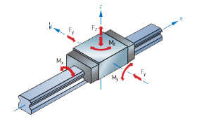
Combined static load
A linear guide can experience forces in both the Y and Z directions, and moments can occur around any of the three axes (X, Y, or Z). This article explains how to determine the combined static load for each of the four most common rail/bearing arrangements.
Mean equivalent dynamic load
Many applications involve loads that change multiple times, or even constantly, during a move cycle. This guide explains how to account for these changing loads by calculating the mean equivalent dynamic load.
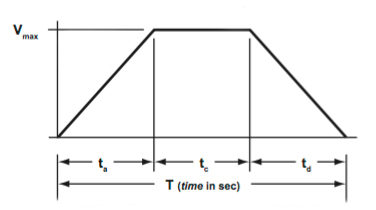
Velocity
The two fundamental move profiles are triangular and trapezoidal. This article explains the geometry of each and how to calculate an application’s maximum and average velocity, depending on the move profile.
Acceleration
When sizing a linear system, a lot of attention is given to velocity, but acceleration often has a greater effect on the system and its components. Here, we explain how to calculate the acceleration required for both triangular and trapezoidal move profiles.
Drive torque
One of the most important factors when sizing a motor is the required torque. This article explains how to determine both the intermittent and the continuous (RMS) torque for motor sizing.
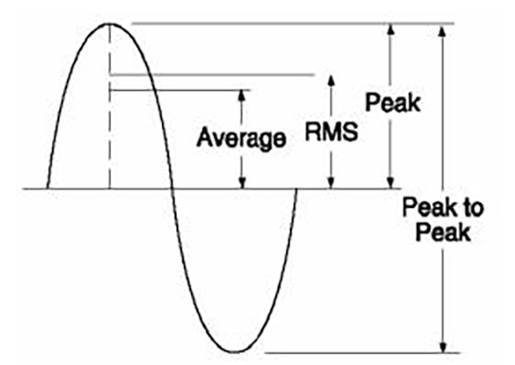
RMS torque
This tutorial explains how to calculate root mean square (RMS) torque, which is used to determine the continuous duty operating region for motor sizing.
Torque with keyed shafts
Adding a keyway to a shaft reduces its effective diameter, and therefore, the amount of torque it can transmit. This article explains how to calculate the permissible torque with a keyed shaft, and how to avoid both shear and crushing failure of the key.
Inertia ratio
The load-to-motor inertia ratio is important for determining how well a motor can control a load during acceleration and deceleration. Here, we show how to calculate the inertia ratio – with and without a gearbox included – and explain why a “perfect” 1:1 ratio isn’t always best.
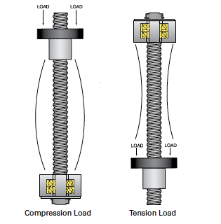
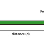
Screw buckling
Buckling is an important consideration when ball or lead screws are used in vertical applications. This guide explains how to calculate the maximum compressive (buckling) load on a vertical screw.
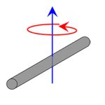
Screw back driving
Another consideration when using a ball or lead screw in a vertical application is its ability to back drive. This guide explains why ball screws are more likely to back drive than lead screws (given the same screw diameter and pitch) and shows how to calculate the back driving torque.
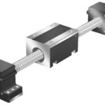
Feature image credit: FOX


Leave a Reply
You must be logged in to post a comment.