There are few linear motion applications in which the load is perfectly centered over the supporting bearing. On the contrary – the majority of applications involve loads that are cantilevered, meaning they are offset from the bearing and induce a moment load.
In this context, the term “bearing” can mean a single bearing or a bearing system – for example, two rails in parallel, with two bearings each, that collectively support a load.
The moment caused by a cantilevered load (or driving force) produces two reaction forces on the bearing that are equal and opposite in magnitude. These reaction forces, multiplied by the bearing’s coefficient of friction, determine the friction forces that oppose the bearing’s motion. In order for the bearing to move, the driving force must be greater than the friction forces; otherwise, binding, or a lack of motion, occurs. Counterintuitively, the solution to overcome binding is not to apply a larger driving force. The solution lies in what is commonly referred to as the 2:1 ratio (also known as the “2:1 rule” or the “binding ratio”).
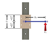
The 2:1 ratio is the relationship between the length of the bearing and the distance that the cantilevered load (or driving force) is located from the bearing. In reality, the 2:1 ratio is not always 2:1. As shown by the equation below, the acceptable relationship between the moment arm distance (D1) and the bearing length (L1) that will prevent binding depends on the bearing’s coefficient of friction (μ).
![]()
Using the generally accepted coefficient of friction of 0.25 for plain bearings, the ratio is 2:1. If the coefficient of friction is lower, at 0.10 for example, the ratio will be 5:1. And if it is higher, at 0.50, for example, the ratio becomes 1:1.
This is why recirculating bearings rarely experience binding issues with cantilevered loads – their coefficient of friction is generally around 0.001, so the acceptable ratio of moment arm distance to bearing length is 500:1.
This white paper from PBC Linear provides an analysis of the forces on the bearing and gives the complete derivation of the 2:1 ratio.
As mentioned above, when the 2:1 ratio is exceeded, applying a larger driving force won’t cause the bearing to move. The only ways to counteract binding are to 1) shorten the moment arm distance, 2) increase the length of the bearing, or 3) reduce the coefficient of friction.
An important design guideline for plain bearing systems is as follows: When two rails or shafts are used (as in the 2-rail, 4-bearing arrangement shown below), the bearings mounted on the rail closer to the cantilevered load (or driving force) should be fixed, and the bearings mounted on the rail farther away from the cantilevered load (or driving force) should be floating. The fixed-floating arrangement allows the bearing system to compensate for small misalignments and helps to prevent unnecessary wear.
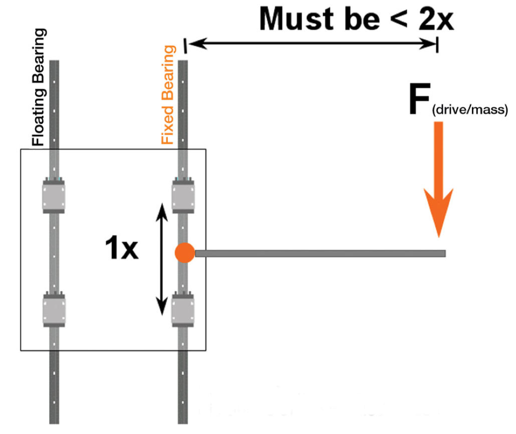
Image credit: igus
Binding or stick-slip?
Binding is sometimes confused with stick-slip, but the two conditions are not the same. Binding is a complete prevention of motion, while stick-slip is intermittent, or “jerky,” motion. In addition to the usual culprits of misalignment and unexpected process forces, another factor that can cause stick-slip motion is the disparity between static and dynamic coefficients of friction. This is especially true for plain bearing systems, because plain bearings tend to have noticeably different static and dynamic coefficients of friction, unlike recirculating bearings, whose static and dynamic coefficients of friction are very similar.
Feature image credit: igus




Leave a Reply
You must be logged in to post a comment.