
When measurements are made to discrete product on the fly, it’s key that the motion system minimize error and correct for the rest.
Brian Handerhan | Business development manager • Life sciences
Patrick Lehr | Product manager • Precision mechanics
Electromechanical & Drives Division • Parker Hannifin Corp.
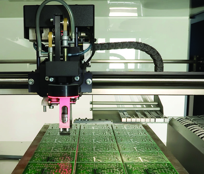
Dynamic metrology is the collection of data on objects traveling on moving machine axes. It’s increasingly common with laser-based inspections and spectrometry, and primarily for semiconductor and electronics manufacturing that uses line scanning of discrete product during various processes. Life-science applications such as cell analysis or DNA and gene sequencing — which necessitate high data-collection throughput — also employ dynamic metrology. Yet another application is in precision laser cutting.
Because the stages carrying the product are in motion during measurements, they must exhibit minimal linear errors, Abbe errors, and planar errors. Sources of these errors abound — and include linear-slide and assembly machining inconsistencies, bearing inconsistencies, friction, deflection, thermal fluctuation, inconsistent feedback, and mechanical windup.
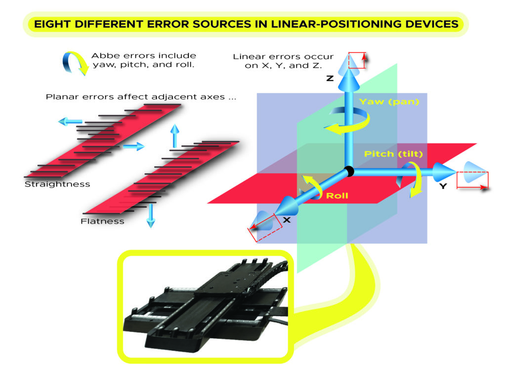
For linear-positioning devices, industry quantifies such error in eight different ways. Abbe errors occur in pitch, yaw, and roll directions; they are significant contributors to accuracy and repeatability and are quantified with angular measures. Linear errors in the X, Y, or Z directions relate directly to the accuracy and repeatability and are quantified with linear measures. In contrast, planar errors occur in X, Y, or Z direction and contribute directly to the adjacent axis in a multi-axis system. These are also quantified with linear measures.
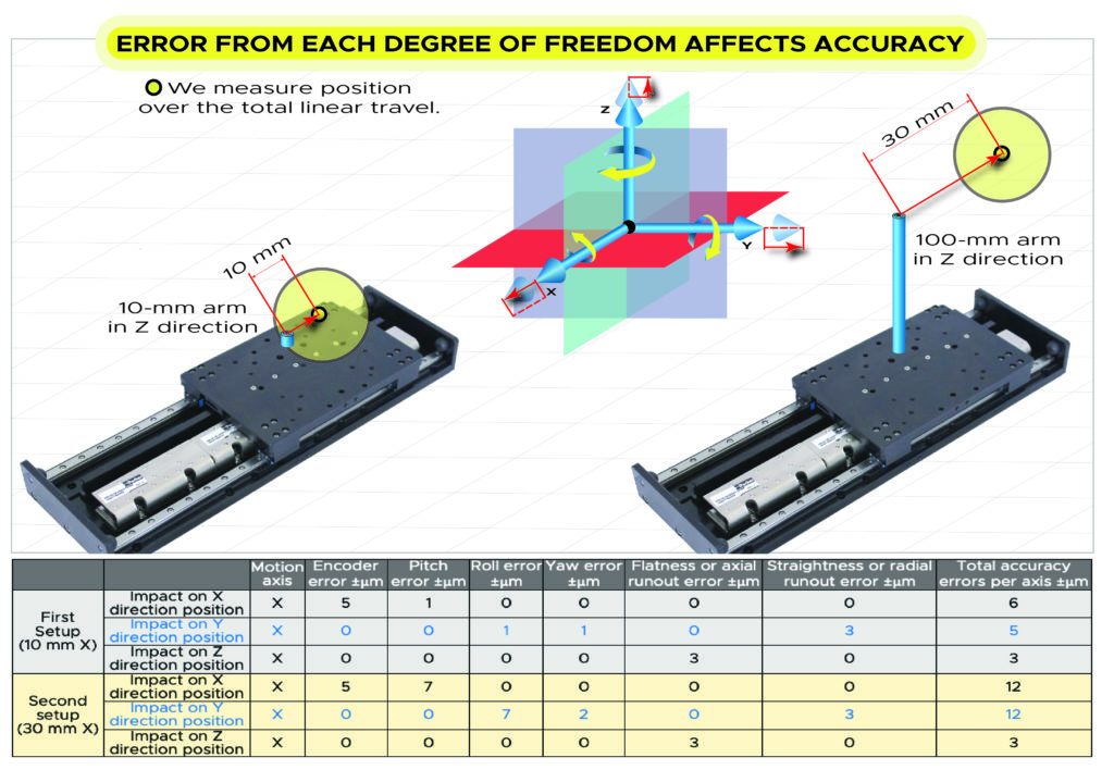
One special note: Accuracy is affected when the measuring point rides at some distance from stage … and total error is higher when the point of measurement is more distant from the stage. In such applications — where the point of interest is some distance from pitch, yaw, or roll points — minimizing Abbe error is most critical. Design engineers must account for such magnification of such errors when specifying linear stages for dynamic metrology applications.
Motion control complements mechanical accuracy
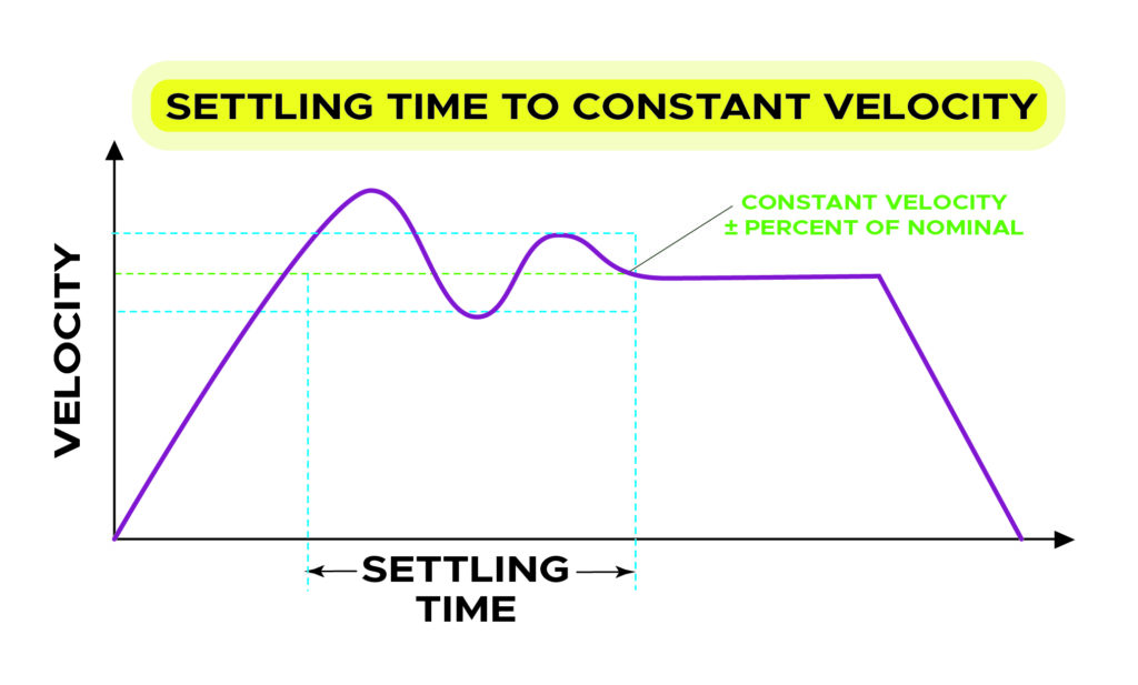
Also necessary for dynamic metrology is tight control over motion-stage speed. Error in the form of unexpected acceleration and deceleration (as velocity ripple) makes the accurate and consistent collection of results in dynamic-metrology setups impossible. Scanning applications in particular need good velocity control or risk poor data collection (relative to expected position) and blurry results.
Causes of velocity ripple include deviations in the mechanical drivetrain; leadscrew, or pulley pitch variations; and friction changes over the travel stroke. Other factors that can cause velocity ripple include accuracy error in the feedback device, a current control limitation in the motor drive; a PWM frequency instead of a linear amplifier; and sub-optimal servo algorithms and control update rate.
There are several ways to minimize torque ripple at stage axes: Install a high-resolution linear-feedback device on the actuator; install a very low sub-divisional error (SDE) encoder on the axis motor; or employ a drive controller with a high servo-update rate.
Holding velocity stable during dynamic-metrology processes can be done in a few ways. One option is to use linear-motor actuators for a quick-response drive and velocity corrections sans drivetrain pitch or friction problems. Another is to install a very low sub divisional error (SDE) encoder — for which position errors occur between hard counts of the encoder. Otherwise, linear feedback on the actuator maybe in order. Another technology helpful to dynamic-metrology is a drive controller with a high servo update rate — capable of quick velocity measurements and corrections.
Applying stages actuated by linear motors for dynamic metrology
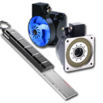
Most actuation of high-speed dynamic-metrology applications is through stages driven with linear motors — ironless linear motors in particular. Because the linear motors in such stages directly couple to the load, there’s minimization or even total elimination of the backlash, efficiency losses, and positional inaccuracies of belt and ballscrew-driven arrangements.
What’s more, linear motors are typically more compact than other drivetrains. That makes for smaller machines with higher stiffness — for lower positional errors and a lightweight design capable of high speeds.
Linear-motor actuators also hold the tightest control over high speeds … even necessitating consideration of encoder sub-divisional errors and servo-position control loops in some cases. Where these are addressed and optimized, linear motors can avoid velocity-ripple issues to deliver quick actuation. At reasonable commercial cost, engineers can optimize systems to achieve following errors to 200 nm at aggressive dynamic-metrology speeds. But to minimize velocity ripple, the engineer must have the application’s speed and sampling rate before specifying encoder resolution and servo sampling rate.
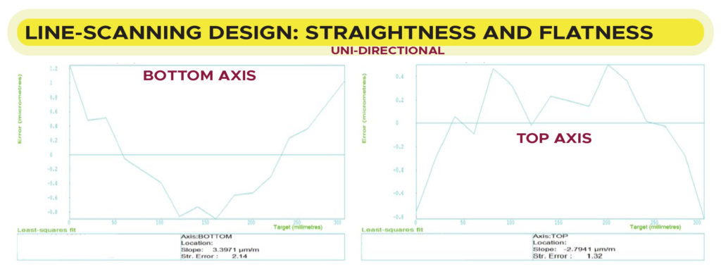
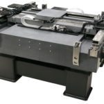
Consider one application for which a design engineering team in the semiconductor market performs laser line-scanning. Assume the process depends on flatness and straightness — with errors not exceeding ±4 µm over a 300 x 300-mm travel zone. Here, wide-base monolithic stages in X-Y systems from some manufacturers can maintain high stiffness for minimal flatness and straightness errors.
Consider another line-scanning application and assume scanning frequency of 100 Hz. Also assume velocity ripple must be below ±2% at stroke speeds of 10 mm/sec. That means position error must stay within ±0.2 mm/sec/100 Hz — or 0.002 mm per 0.01 sec. So here, the stage actuator needs an encoder with resolution exceeding allowable position error … a 2-µm encoder at least. Plus the servo-update rate must be at least tenfold the required correction rate (0.01 second times 10 = 1-msec update rate). Here, only stages with precision encoders and certain servo drive and controller combinations can hold velocity to within requirements.
In fact, only linear-motor actuated stages can meet the critical specifications of dynamic metrology. Look for suppliers of these systems that supply laser-interferometer test reports to confirm each stage’s ability to outperform other drivetrain mechanisms and deliver metrology-level performance.
Parker Hannifin | solutions.parker.com/LP=12738


Leave a Reply
You must be logged in to post a comment.