
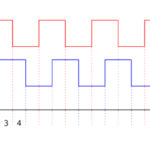
Encoders that provide incremental position measurements (whether rotary or linear) output two signals, or channels, typically termed “A” and “B,” to provide position and direction information. These output signals can be in the form of analog sine and cosine waves or in the form of digital square waves. Those that produce digital output signals are typically referred to as simply “incremental encoders,” while those that produce analog output signals are referred to as “sine-cosine encoders.”
Incremental encoders for digital output signals
Incremental encoders can provide any of several types of digital output signals, but the two most common are high transistor logic (HTL) and and transistor-transistor logic (TTL).
Incremental encoders with high transistor logic (HTL) output generate the output signal using two transistors in a totem-pole configuration. When the output is active, in the logic “high” state, the output voltage equals the supply voltage, so the transistors are “pushing” or “sourcing” the output signal to the load. When the output is off, or in the logic “low” state, the output voltage equals the supply common voltage level, in effect “pulling” or “sinking” the output signal from the load. This is why HTL output is sometimes referred to as “push-pull” output.
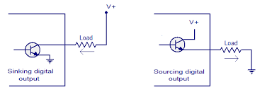
Image credit: circuitstoday.com
The supply voltage for HTL output encoders can range from 10 to 30 VDC, with 24 VDC being common. These encoders are often used when the controller requires a 12 or 24 V signal for the feedback input, or when the input voltage to the encoder is variable.
Incremental encoders with transistor-transistor logic (TTL) output provide a 5 VDC signal when the output is in the logic “high” state, regardless of the supply voltage, which can range from 4.5 to 5 VDC or from 10 to 30 VDC. When the output is in the logic “low” state, the output signal is 0 VDC.

Because TTL output encoders always use differential (complementary) signals, they’re sometimes referred to as “differential line drivers” or “balanced differential line drivers,” and are compliant with the RS422 standard when operated with a 5 VDC supply. TTL output encoders have very good noise immunity due to the differential signals, and so can operate reliably with long cable runs.
The term “line driver” refers to the fact that the circuit can source, or drive, current down the line, or signal cable.
Sine-cosine encoders for analog output signals

Image credit: Texas Instruments
Sine-cosine encoders are very similar to incremental encoders, except the output signals are 1 Vpp (Volt peak-to-peak) sine and cosine waves, rather than digital square wave pulses. The high quality of sin-cos signals allows high levels of interpolation, for better resolution and better control of position and speed.
In a type of encoding referred to as X4 encoding, resolution can be increased fourfold by counting the number of zero crossings of each waveform (sine and cosine) during each period. This type of encoding is also possible, — and common — with the digital output of incremental encoders, but because analog encoders use continuous sinusoidal waveforms rather than stepped, digital waveforms, the signals of sine-cosine encoders can be interpolated to a higher degree for better resolution.
Sine-cosine encoders are often used in servo systems, where high resolution is required for extremely accurate position and speed control. Analog output signals are, however, more prone to noise than digital signals, so it’s common for sine-cosine encoders to produce differential output signals to remove noise.

Leave a Reply
You must be logged in to post a comment.