Resolution is one of the most important indicators of an encoder’s performance. For incremental encoders, resolution is typically specified in pulses per revolution (PPR), or, in the case of linear encoders, pulses per inch (PPI) or pulses per millimeter (PPM). These square-wave pulses are very precisely spaced, and the encoder determines its position by counting the number of pulses generated during a movement.
The resolution of a linear encoder can also be specified in terms of microns, which refers to the distance between pulses.
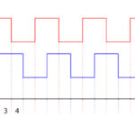
When an incremental encoder outputs just one set of pulses, only position can be determined – not direction. This is why most incremental encoders use quadrature encoding, which produces two sets, or channels, of pulses – A and B – that are out of phase from each other by 90 degrees (hence the term “quadrature”). With two sets of pulses, the encoder can determine both position and direction, based on which channel is leading and which is trailing. And, with quadrature output, any one of three types of encoding can be employed: X1, X2, or X4.
X1 encoding counts either the rising or falling edge of channel A.
X2 encoding counts both the rising and falling edges of channel A are counted. And with twice the edges counted, the encoder’s resolution is doubled. So a 1000 PPR encoder that uses X2 encoding has a resolution of 2000 PPR.
X4 encoding counts both the rising and falling edges of both channels A and B. This provides a four-fold increase in resolution, since now, four edges are counted.

Image credit: National Instruments Corporation
When a rotary encoder is used to measure linear distance, the required encoder resolution (PPR) can be found by dividing the lead of the screw or pulley (distance traveled per revolution) by the linear resolution required by the application.
![]()
For example, if the required linear resolution is 10 microns (0.01 mm), and a screw with a 25 mm lead is used, the encoder resolution should be 2500 PPR (or higher).
![]()
If the encoder uses X2 or X4 encoding, the encoder’s required PPR should be divided by a factor of 2 or 4, respectively. For example, if the application calls for an encoder that has a resolution of 2500 PPR, but X4 encoding is being used, then the encoder’s actual resolution only needs to be 625 PPR (2500 ÷ 4).
Once the encoder’s resolution has been determined, its maximum speed – both mechanical and electrical – needs to be considered. The mechanical speed is limited by the potential for physical damage to the encoder, whereas the electrical speed is limited by its frequency response, which is the maximum speed at which the encoder’s electronics can switch between “on” and “off.” Mechanical speed is specified in rotations per minute (rpm), but the electrical speed is determined by dividing the frequency response, which is specified in Hz or kHz, by the encoder’s resolution.
![]()
For example, if a 2500 PPR encoder has a maximum mechanical speed of 3000 rpm, a frequency response of 100 kHz, and is used with X1 encoding, its maximum electrical speed will be 2400 rpm.
![]()
In this case, the maximum electrical speed (2400 rpm) is less than the maximum mechanical speed (3000 rpm), so electrical speed is the limiting factor.
Again, if X2 or X4 encoding is used, it must be factored into the maximum electrical speed, by multiplying the encoder’s stated PPR by 2 or 4, respectively.
In the example above, if X2 encoding is used, then the PPR will be 5000, and the maximum electrical speed will drop to 1200 rpm. This is an important step when determining maximum electrical speed, because the encoder electronics must be able to switch fast enough to keep up with the encoder’s output.


Leave a Reply
You must be logged in to post a comment.