When choosing an encoder for motion applications, a few specifications immediately come to mind. What sensing technology should you use? What accuracy and resolution do you need? Does the application require incremental or absolute position feedback? But one specification that is sometimes overlooked during sizing and selection is the maximum encoder speed.
Like any electrical component, delays in switching and processing time limit the speed at which an encoder can operate. This limitation in speed due to internal electronics is referred to as the encoder’s maximum electrical speed, and applies to both linear and rotary encoders with either magnetic or optical sensing technologies.
As an encoder moves — rotationally or linearly — internal electronics switch on-and-off in response to changes in light (for optical types) or magnetism (for magnetic types). This electronic switching produces a digital signal (or a binary word, for absolute encoders) indicating the encoder’s position. The maximum speed at which its electronics can change state (from “on” to “off” or vice-versa) is known as the encoder’s frequency response.
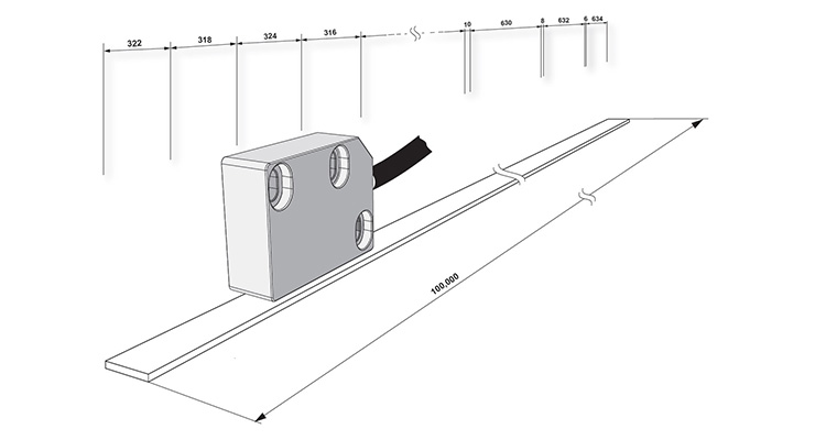
The maximum electrical speed is directly proportional to the encoder’s frequency response and inversely proportional to the encoder’s pulses per revolution (PPR) for rotary encoders, or pulses per distance (typically pulses per millimeter, PPM) for linear designs.
In addition to the maximum electrical speed, rotary encoders are also limited by a maximum mechanical speed. The maximum mechanical speed primarily depends on the speed capability and lifetime of the bearings that support the encoder as it rotates. Exceeding the encoder’s maximum mechanical speed (specified by the manufacturer) can result in physical damage to the encoder or a shortened service life.
How to calculate maximum encoder speed
For rotary encoders, the maximum rotational speed is determined by dividing the encoder’s maximum frequency response by its pulses per revolution (PPR).
![]()
For linear encoders, the maximum linear speed is determined by dividing the frequency response by the number of pulses per distance (typically PPM).
![]()
How quadrature encoding affects encoder speed
To improve resolution, incremental encoders often produce two signals in quadrature and count both the rising and falling edges of one signal — known as X2 encoding — or the rising and falling edges of both signals — known as X4 encoding. It’s important to remember that when X2 or X4 encoding is used, the encoder’s pulses per revolution (or per distance) must be multiplied by either “2” or “4” accordingly, since the electronics will have to switch two or four times as quickly.
You can see from the equations above that although increasing the pulses per revolution (or per millimeter) improves resolution, it reduces the encoder’s maximum speed.
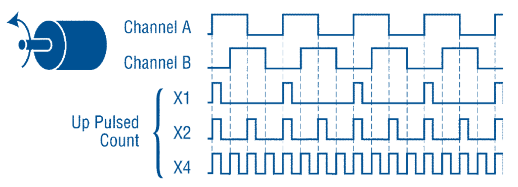
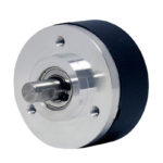
Image credit: Danaher
Regardless of the resolution, sensing technology, output type, or encoder design, if the encoder’s maximum electrical speed is lower than the speed required by the application, an encoder with a higher frequency response will need to be selected.
Feature image credit: Renishaw plc


Interesting!
How is this done with a SinCos resolver/encoder(analog)? Thanks for you’re article!