Options abound for tracking or measuring the position of a linear system — from magnetic and optical linear encoders that read changes in magnetism or light, to linear variable differential transformers that operate on the principle of mutual induction, to magnetostrictive sensors that rely on torsional strain induced by magnetic fields.
But each of these technologies requires that a critical part of the measuring system be attached to the object being tracked. What if the environment, application, or installation space doesn’t permit attaching critical measuring equipment — such as a read head, push rod or magnet — to the target object? Another type of linear measuring device, known as a draw-wire sensor, solves this problem.
Some other names for draw-wire sensors include: draw wire transducers, cable transducers, string potentiometers, string encoders, linear position string pots, and yo-yo pots or yo-yo encoders (due to the way the spring-wired drum pulls the wire back when it’s removed from the load).
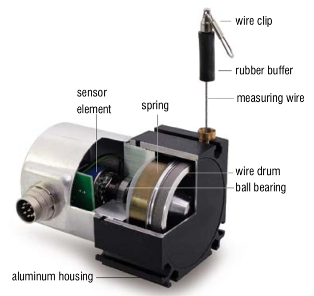
Image credit: Micro-Epsilon
Draw-wire sensors are relatively simple in construction, with four main parts: a measuring wire, a drum (aka spool or reel), a spring, and a position sensor.
The measuring wire is commonly made of braided steel or stainless steel and covered with nylon or polyamide, although wires can be made of plastic and other materials for harsh environments or special application requirements. The passive wire connects to the object being measured by a clevis or loop, and the wire is mechanically attached to and single-wrapped around a precision-machined drum. Threading on the drum guides the wire to ensure consistent unwrapping and retraction without overlap, maintaining the exact relationship between the wire’s motion and the linear distance traveled. A coiled spring maintains tension in the wire to prevent sagging, especially in horizontal applications. A sensor is attached to the axle of the drum and measures the drum’s rotation.
When the target object moves, the wire is extended (or retracted), and the drum rotates. The sensor measures this rotation and outputs a position signal proportional to the drum’s rotation, and therefore, to the wire’s movement. The type of sensor used depends on the application requirements, with common choices being optical or magnetic encoders, with incremental or (for longer measuring lengths) absolute output. For applications that require an analog signal, potentiometers can also be used.
Draw-wire sensors can measure distances up to 50 km (50,000 m) and can operate with wire extension and retraction speeds up to 10 m/s and acceleration rates up to 5 g. One of the most important specifications when choosing a draw-wire sensor is linearity, which refers to the difference between the ideal output-position plot (a straight line) and the sensor’s actual output-position plot. Draw-wire sensors typically range in linearity from ± 1% to ± 0.05% of the measuring range, but designs are available with linearity of ± 0.01% of the measuring range.

Image credit: SpaceAge Control
A unique property of draw-wire sensors is that they can measure linear distance even with indirect measuring paths. When the measuring path is not a straight line, low-friction, high-precision pulleys, or guide rollers, can be used to create diversions without jeopardizing the measurement’s integrity.

Image credit: Micro-Epsilon
Draw-wire sensors are simple, rugged (available in IP67, IP68, and IP69K protection classes), and low-cost. They’re an ideal solution for applications with intermittent measuring requirements, but generally aren’t recommended for applications with high or continuous duty cycles. Typical applications include patient beds, hydraulic and pneumatic actuators, lifting devices, and mobile equipment such as forklifts and construction machinery.
Feature image credit: Baumer


Leave a Reply
You must be logged in to post a comment.