
In a previous post, we looked at the stress-strain curve and its relationship to various aspects of material strength — tensile strength, yield strength, and fracture mechanics strength, for example. And while we often think of materials and structures in terms of strength, technically, “strength” is a measure of how much force a material can withstand before permanent deformation or failure occurs. For proper running of linear guides, actuators, and other motion components, however, it’s typically more important to know how much deflection the object will experience under a given load — in other words, the more important property is the object’s stiffness.
A material’s stiffness indicates its ability to return to its original shape or form after an applied load is removed.
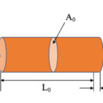
When a material is subjected to a load — its own unsupported weight, an external applied load, or both — it experiences stress and strain. Stress (σ) is an internal force on the material caused by the load, and strain (ε) is the deformation of the material that results from this stress. The ratio of stress (force per unit area) to strain (deformation per unit length) is referred to as the modulus of elasticity, denoted E.
![]()
The ratio of stress to strain is also referred to as a material’s elastic modulus, tensile modulus, or Young’s modulus.
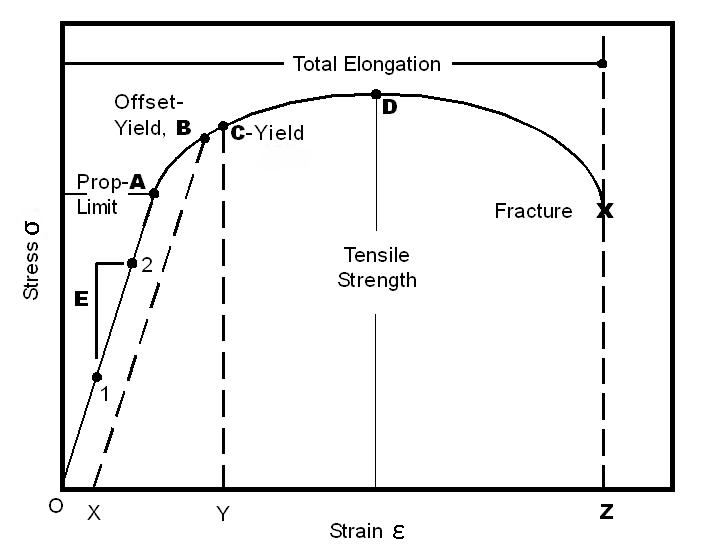
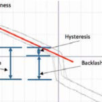
According to Hooke’s Law, the modulus of elasticity is the slope of the linear portion of the stress-strain curve, up to the proportional limit (also referred to as the “elastic limit”), labeled below as point A.
A material that is strong can withstand high loads without permanent deformation. A material that is stiff can withstand high loads without elastic deformation. Another material property sometimes confused with strength or stiffness is hardness. Hardness defines a material’s ability to resist localized (surface) deformation, often due to friction or abrasion.
Unlike strength, a material’s stiffness, or modulus of elasticity, is an inherent property of the material, and external factors such as temperature or material processing have very little effect on its value.
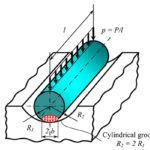
It’s important to note, however, that in practical applications, the stiffness of a structure depends on both the material’s modulus of elasticity and the structure’s geometry in terms of planar moment of inertia (also referred to as second moment of area). Planar moment of inertia, I, expresses how the material’s area is distributed around the axis of motion.
The product of modulus of elasticity and planar moment of inertia is sometimes referred to as the material’s flexural rigidity (EI).
In equations for deflection, both stiffness factors — the modulus of elasticity (E) and the planar moment of inertia (I) — appear in the denominator. This makes sense because deflection is inversely related to stiffness.
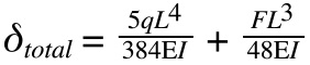
Image credit: wikipedia.com
In other words, the higher the material’s modulus of elasticity and the higher the object’s planar moment of inertia, the less the structure will deflect under a given load.

Just curious if there is any relation between deflection and yield strength of beam/material? For me, it should be yes because. . . .
Deflection = (5/384) x q L^4 / (EI)
Or
(8×5/384) x ( qL^2/8) / (EI)
Or
0.104 x M / ( EI)
Where M is bending moment for simply supported beam
Or
(0.104/E) x f /y
Where flexural stress = f = M.y/I
So deflection is directly proportional to f, which is in design code stated as 0.6 Fy.
Fy=yield strength