
If your application calls for a Cartesian robot, you have a wide variety of options, depending on the level of integration you want to undertake. And although pre-engineered Cartesian robots are becoming more widely adopted as manufacturers expand their product ranges to fit a broader scope of performance criteria, some applications still necessitate building your own Cartesian system — for example, to meet special environmental conditions or to fulfill a highly specialized set of performance requirements.

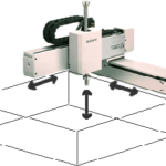
Here are a few examples of 3-axis Cartesian systems from IAI.
But “build your own” doesn’t necessarily mean “build from scratch.” Case in point: the key components of a Cartesian robot — the linear actuators — are available in numerous configurations, so it’s rarely necessary to build the actuators from scratch. And many linear actuator manufacturers offer connecting kits and mounting brackets that make assembling your own Cartesian system from catalog-spec actuators a relatively simple exercise.
However, determining the basic layout and choosing the appropriate linear actuators is only the first step. To avoid ending up with a Cartesian system that doesn’t perform to the application requirements or doesn’t fit in the expected footprint, keep the following considerations in mind — especially during the design stage.
System configuration
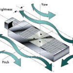
One of the first things to specify when designing a Cartesian robot is the configuration of the axes, not only to achieve the necessary movements, but also to ensure the system has sufficient rigidity, which can affect load-carrying capacity, travel accuracy, and positioning accuracy. In fact, some applications that require movement in the Cartesian coordinates are better served by a gantry robot than by a Cartesian system, especially if the Y axis requires a long stroke or if the Cartesian arrangement would put a large moment load on one of the axes. In these cases, the dual-X or dual-Y axes of a gantry system may be necessary to prevent excessive deflection or vibration.
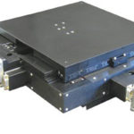
If a Cartesian system is the best solution, the next design option is typically the drive unit for the actuators — with the most common choices being a belt, screw, or pneumatic-driven system. And regardless of the drive system, linear actuators are typically offered with either a single linear guide or dual linear guides.
The vast majority of Cartesian robots use the dual-guide configuration, since it offers better support for overhung (moment) loads — but axes with dual linear guides will have a wider footprint than axes with single linear guides. On the other hand, dual-guide systems are often shorter (in the vertical direction), which can prevent interference with other parts of the machine. The point is, the type of axes you choose affects not only the performance of the Cartesian system, it also affects the overall footprint.
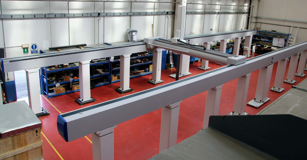
Image credit: Coord3
When thinking about the system’s footprint, don’t forget about end effectors or end-of-arm (EOA) tooling that will need to be incorporated. It’s important to consider this early in the design stage to ensure there are no interferences between tools such as grippers or dispensing heads and the other components of the Cartesian system or the machine itself.

Image credit: Fisnar
Cable management
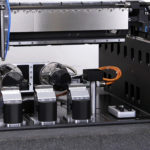
Another important aspect of Cartesian robot design that’s often overlooked in the early phases (or simply deferred to later phases of the design) is the cable management. Each axis requires multiple cables for power, air (for pneumatic axes), encoder feedback (for servo-driven Cartesians), sensors, and other electrical components. And when systems and components are integrated into the Industrial Internet of Things (IIoT), the methods and tools for connecting them becomes even more critical. All of these cables, wires, and connectors must be carefully routed and managed to ensure they don’t experience premature fatigue due to excessive flexing or damage due to interference with other parts of the system.
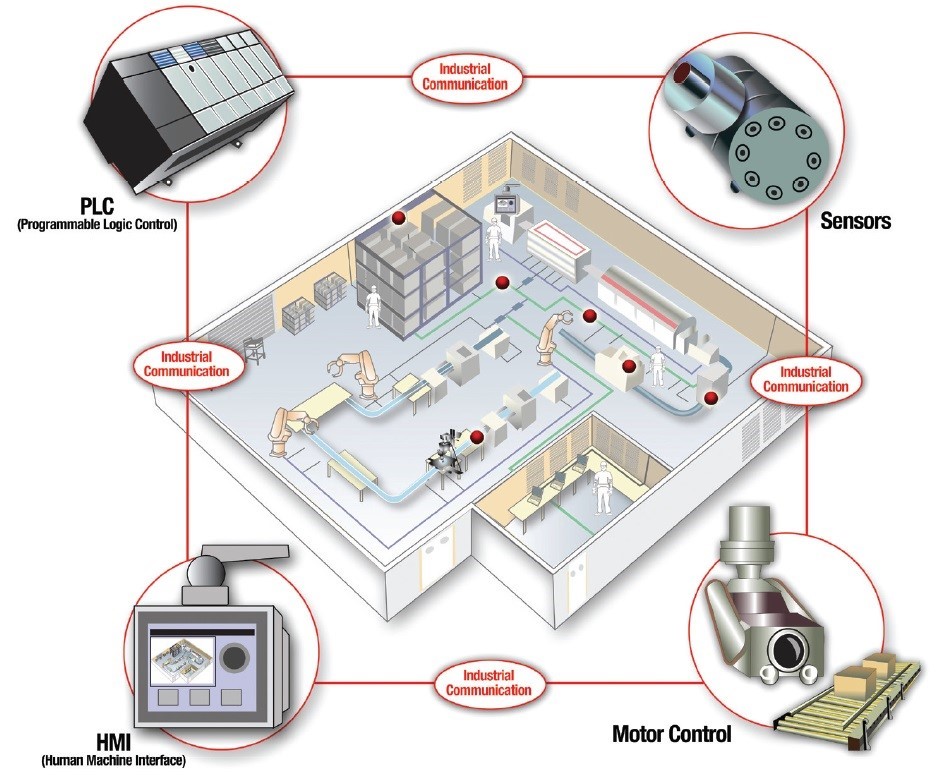
Image credit: Texas Instruments
Cartesian (as well as SCARA and 6-axis) robots make this connectivity even more challenging, since the axes can move both independently and in synchronization with each other. But one thing that can help mitigate the complexity of cable management is to use components that reduce the number of cables required — for example, motors that integrate power and feedback into a single cable, or integrated motor-drive combinations.
The type of control and the network protocol can also influence the type and quantity of cables required and the complexity of cable management. And don’t forget that the cable management system — cable carriers, trays, or housings — will affect the dimensions of the overall system, so it’s important to check for interference between the cable management system and the other parts of the robot and the machine.
Controls
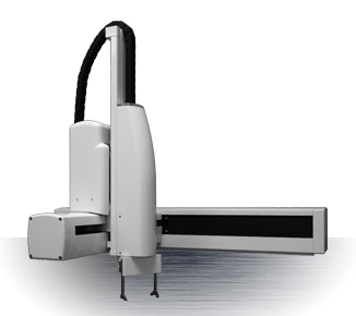
Image credit: Precise Automation
Cartesian robots are the go-to solution for point-to-point moves, but they can also produce complex interpolated moves and contoured motion. The type of motion required will help determine what control system, networking protocol, HMI, and other motion components are best suited for the system. And although these components are, for the most part, housed separately from the axes of the Cartesian robot, they will influence what motors, cables, and other on-axis electrical components are required. And these on-axis components will, in turn, play a role in the first two design considerations: configuration and cable management.
So the design process comes “full-circle,” reiterating the importance of designing a Cartesian robot as an integrated electromechanical unit, rather than a series of mechanical components that are simply connected to electrical hardware and software.

Leave a Reply
You must be logged in to post a comment.