
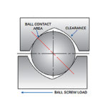
When you think of a ball screw assembly, you probably envision a screw shaft with a motor connected to one end. The motor turns the screw, and the ball nut travels along the length of the screw shaft.
An alternative setup is to hold the screw shaft stationary and rotate, or drive, the ball nut instead of the screw. Rotating ball nut assemblies (also referred to as driven nuts) were once found only as specialty solutions, cobbled together by end users or provided as custom assemblies by manufacturers. But now, virtually all mainstream ball screw manufacturers offer rotating ball nuts as standard catalog items.
Characteristic speed vs. critical speed
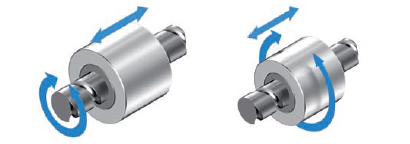
In a traditional ball screw assembly, the maximum travel speed is limited by the critical speed of the screw shaft — i.e. the speed at which the screw begins to experience resonance, causing the screw to whip. The critical speed of a screw shaft is determined by its length, diameter, and end support bearings.
nc = critical speed (rpm)
k = factor based on end support bearings
dn = root diameter of ball screw (mm)
Lcr = unsupported length of ball screw (mm)
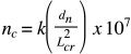
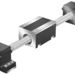
In a rotating ball nut assembly, the screw is stationary and the nut is rotated, typically by a motor that is attached to the nut via a belt and pulley system. Support for the ball nut is provided by a high-capacity radial bearing. Because the screw is stationary, resonance, and therefore, critical speed, are no longer limiting factors. Instead, the assembly’s maximum speed is determined by the characteristic speed, or DN value, of the ball nut.
The characteristic speed is governed in part by the speed of the balls as they travel through the nut, which depends on the ball nut design and ball return method. Typical DN values range between 60,000 and 150,000 mm/min, based on the type of ball nut. (Ball nuts with internal recirculation generally have higher DN values than ball nuts with external recirculation.)
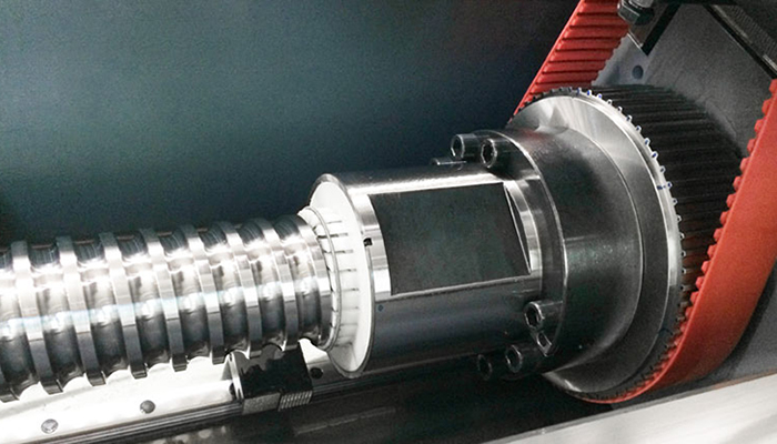
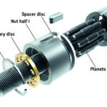
Image credit: A. Mannesmann Maschinenfabrik GmbH
The driven nut’s maximum rotary speed (nmax) can be determined from the characteristic speed, or DN value. (Note that the published maximum speed may be lower, due to limits imposed by the radial support bearing or by other ball nut design factors.)
![]()
DN = characteristic speed (mm/min)
nmax = maximum rotary speed (rpm)
d0 = nominal diameter of screw (mm)
Rigid mounting vs. end bearing supports
Stationary screws do not require end support bearings; instead, the screw is rigidly mounted at each end, which provides two benefits. First, torsional moments are transmitted to the fixed mounting structures rather than being transmitted to the screw. This improves the rigidity of the assembly. Second, it is relatively easy to tension a stationary screw (as opposed to a rotating screw) to allow it to compensate for expansion and contraction due to temperature fluctuations.
It’s also worth noting that because the screw shaft remains stationary, a hollow screw with internal cooling can also be used in a rotating nut assembly, for applications where extreme heat or wide temperature fluctuations are present. However, internal cooling mechanisms add complexity to the design.
Moving nut assembly vs. moving screw
Rotating nuts are most often used in applications that require high travel speeds over long lengths. Driving a long screw shaft, as in a traditional ball screw assembly, means dealing with high rotational inertia. Because the rotating ball nut design drives only the nut assembly — not the entire length of screw shaft — inertia is greatly reduced, which helps optimize the inertia match between the motor and the load and improves system dynamics.
Image credit: SKF Group
But driving the ball nut means the belt-pulley-motor assembly must move along the screw shaft with the nut, so the footprint of entire assembly must be taken into account when designing the surrounding structures. The moving motor assembly also requires a more complex cable management scheme. Another type of rotating ball nut solution, the hollow shaft motor, solves these problems by incorporating the ball nut directly into the motor. But this is a highly specialized solution, since the motor must be designed to accommodate the ball nut.
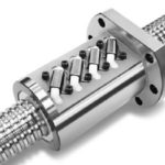
To reduce space and simplify integration for the OEM or end user, some manufacturers machine the raceways for the radial bearing onto the outer surface of the nut, so the balls of the radial bearing rotate between the outer nut body and the inner surface of a housing.
The other technology that meets the combined performance requirements of high thrust force, good positioning accuracy, fast travel speed, and long length is the iron core linear motor. However, iron core linear motors experience cogging forces that degrade the smoothness of motion. They are also vulnerable to contamination by metal chips or flakes, due to their open construction and exposed magnets. Rotating ball nut solutions, on the other hand, are well-suited for applications where chips and dust are present, such as machine tools and woodworking machines. They are also ideal solutions for long, high-load transport applications, where rack and pinion assemblies lack the required positioning accuracy.


Great article. I am resigning a cnc router for wood and would like to use a driven nut application..
Thanks, Joe
I wonder how the linear motion of the ball screw is accomplished, an anti-spin mechanism must be used, but how to make the screw stationary and allow it to move back and forth.
Can the system be designed so that the nut spins (but does not move back and forth)?. The screw would then be driven back and forth (but not rotate). I have an application for this set-up.