
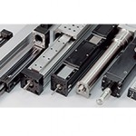
In many applications that require vertical motion, a Z axis actuator is combined with one or two horizontal axes in a Cartesian or gantry-style arrangement. In these multi-axis configurations, the moved load is mounted to the Z axis via a bracket, creating a moment load that affects not only the Z axis, but also the horizontal (X and Y) axes. This cantilevered load can lead to deflection in the supporting linear guides, actuator housings, and brackets, in addition to unacceptable settling times and oscillations in highly dynamic applications. This is why applications that require vertical motion with high rigidity and minimal deflection sometimes use a vertical lift stage rather than a traditional Z axis actuator.
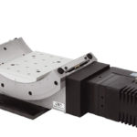
A vertical lift stage uses a flat, horizontal table to support a load as it moves vertically, eliminating cantilevered loads that can cause deflection. There are several design variations of vertical lift stages, but when extremely smooth, accurate travel and high positioning accuracy are the most important criteria, the design will typically consist of a table that is connected to crossed roller slides in a wedge arrangement. A ball or lead screw drives the table in the lateral direction, and the wedge arrangement of the crossed roller slides transforms the horizontal motion from the screw into vertical motion of the table. This design provides very accurate travel and positioning accuracy, but is typically limited to stroke lengths of 25 mm or less.

Image credit: Newport Corporation
This video from Standa shows the operating principle of the screw-driven wedge design.

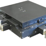
Image credit: Optimal Engineering Systems, Inc.
Another common design for vertical lift stages uses a vertical linear guide at each corner (or in some cases, six linear guides spaced evenly around the area of the table) and a vertical ball or lead screw located in the center. The guides are typically round shafts with recirculating linear bushings, since they provide very smooth motion and have a lower tendency to bind when using four (or more) guides in tandem, thanks to their ability to compensate for some misalignment.
The benefit of this vertical lift stage design is the ability to carry larger and heavier payloads while maintaining smooth, precise motion and good parallelism between the table and base during motion. Available stroke lengths are also longer than for the screw-driven wedge design — up to several hundred millimeters in some cases.
Note that both types of vertical lift described above are termed “stages” because they’re designed for extremely accurate travel and positioning in the Z direction, much like X-Y stages that use high precision linear guides and ball or lead screw drives.
However, in the screw-driven wedge design, the table surface is typically machined to a very tight flatness tolerance, so it more closely fits the traditional definition of a stage than does the screw-driven linear guide version.
Vertical lifts used in material handling and people-moving applications are often referred to as “vertical platform lifts” or — depending on the design — “scissor lifts.”
Feature image credit: IntelLiDrives


Leave a Reply
You must be logged in to post a comment.