
Updated June 2019 || One of the benefits of synchronous belts is their ability to operate with lower tension than their V-belt counterparts. And once the proper tension is determined and applied, synchronous belts rarely need re-tensioning. But improper tension in a synchronous belt drive system — either too low or too high — can lead to poor meshing between the belt and pulleys, belt ratcheting, or even reduced load and acceleration capability.
The proper tension value for a synchronous belt drive system depends on the application — taking into account factors such as the drive torque required for moving the load, the acceleration/deceleration of the belt, and the orientation of travel (horizontal, vertical, or inclined). Manufacturers offer guidelines or suggested “starting values” for belt tension, but often advise real-world testing to determine application-specific tension requirements. To that end, belt applications can generally be classified as:
Motion transfer: In these applications, the torque load on the belt and pulley is relatively light, and the tension is correspondingly low. The primary purpose of belt tension in motion transfer applications is to ensure the belt conforms to and meshes properly with the pulleys.
Power transmission: For general power transmission, loads tend to be variable, with belts experiencing both constant and peak loads. Therefore, power transmission applications tend to require higher belt tension to ensure the belt maintains proper mesh with the pulleys and to prevent the belt from ratcheting under peak loads.
Registration: When belts are used primarily for positioning (registration), the goal is to ensure maximum accuracy from the belt and pulley drive by reducing backlash. Regardless of whether loads are light or heavy, higher tension is often required to increase the belt’s tensile modulus and increase meshing interference with the pulleys.
Once the proper tension value has been determined, there are several ways the actual tension can be measured. One common method involves measuring disturbances in the air surrounding the belt due to vibration.
Similar to a guitar string, a synchronous belt will vibrate at its resonant frequency when it is “plucked,” and the frequency of vibration is directly related to the tension of the belt. Sonic (also referred to acoustic) tension meters sense and record the belt’s vibration when it is plucked, or tapped. The tension force is then calculated based on this vibration frequency, the length of the vibrating belt span, and the mass of the belt.

Image credit: Gates Corporation
![]()
Tst = static tension (N)
f = vibration frequency (Hz)
L = vibrating span length (m)
m = belt mass per unit length and width (kg /m2)
b = belt width (m)
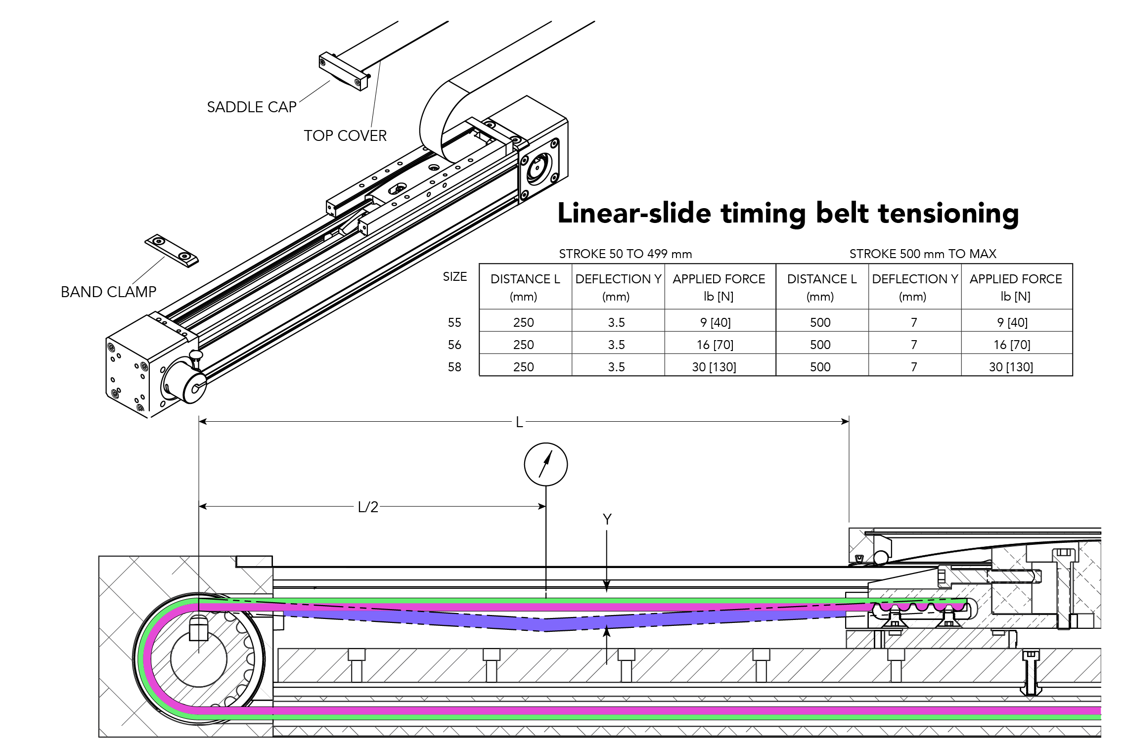
Belt tension can also be measured, or estimated, by causing the belt to deflect by a given amount (typically 1/64 inch per inch of belt span, or 0.4 mm per 25 mm of belt span) with a specified force. Often referred to as the force-deflection method, the minimum and maximum forces necessary to produce the specified deflection for a given tension are calculated via formulas. Note that this method is best used on belts with longer span lengths.

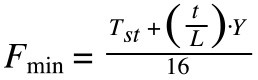
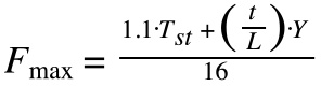
F = Force to produce the specified deflection (N)
Tst = static tension (N)
t = belt span length (m)
L = belt pitch length (m)
Y = tensioning constant based on belt (provided by manufacturer)
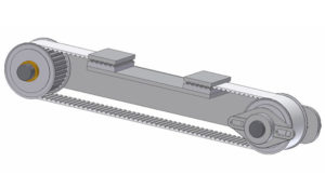
When the belt system uses a simple two-pulley configuration, the distance between the pulley shafts is directly related to the tension on the belt, so this distance can be used to determine the belt tension. This method is often referred to as the shaft separation method. But be aware that if the pulleys have different diameters, the belt spans will need to be added as vectors to determine the resulting tension force.
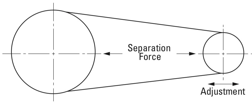
Image credit: Gates Mectrol
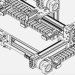
Similar to the shaft separation method, tension can be induced on the belt via the position of the idler pulley. In this method, a force is applied to the idler pulley, causing it to move. A spring or force measuring device indicates when the pulley’s location provides the desired belt tension. Once the pulley position is determined, it is fixed in place to ensure the tension is maintained. Like the shaft separation method, the idler pulley tensioning method may require vector summation of the belt spans if more than two pulleys are used in the system.
In many cases, the force-deflection method is the least accurate, since it’s difficult to measure small deflections, and even for longer spans (and larger deflection values) the process to measure deflection can be cumbersome. The shaft separation and idler pulley methods are typically more accurate, but require vector calculations for systems with multiple pulleys and belt spans.
 Sonic tension measurement devices are simple to use, but ambient noise can interfere with their accuracy. To solve this problem, most devices include a gain adjustment or software that allows the device to “tune out” ambient noise and provide tension measurements accurate to ±10 percent.
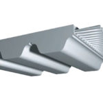
Feature image credit: Brecoflex Co., LLC


Leave a Reply
You must be logged in to post a comment.