
Lead screw sizing is a bit of a hybrid exercise, with similarities to the process of ball screw sizing, but incorporating some of the considerations that come with sizing a plain bearing. While many factors are involved in the selection of a specific lead screw assembly, lead screw sizing — choosing the right diameter and lead for the application — can be done in four simple steps.
1. Determine the axial load
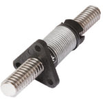
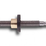
Lead screws are often used in linear actuators and positioning equipment to provide thrust (axial) force to drive a load. The amount of axial force that a lead screw assembly can withstand is determined by the diameter and lead of the screw and the material of the nut — plastic or bronze. Plastic lead screw nuts are often self-lubricating and are less sensitive to chemicals and other contaminants, but they have significantly less load capacity than bronze versions. If the application requires very high axial loads (thrust forces), it may be necessary to use a lead screw assembly with a bronze nut.
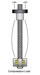
The application’s maximum axial load must also be checked against the load that can be supported by the screw shaft, commonly referred to as the buckling strength or column strength. In horizontal applications, where the load is supported by a low-friction linear guide, the weight of the moved load contributes only a small amount to the axial load on the screw. But in vertical applications, where gravity causes the screw shaft to see the full force of the load, buckling can become a significant factor in lead screw sizing.

Fb = maximum compressive (buckling) load (N)
fb = factor based on end support bearings
dr = root diameter of screw (mm)
Lc = unsupported length of screw (mm)
2. Check the critical speed
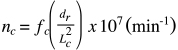
Like ball screws, lead screws have an inherent maximum rotational speed, which is referred to as the critical speed. The critical speed is based on the natural frequency of the screw, and if it is exceeded, severe vibrations can develop and damage the screw assembly.
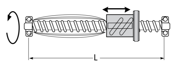
The determining factors for the critical speed of a screw shaft are its length, diameter, and end fixity. (Note that mounting orientation — vertical or horizontal — does not affect critical speed.) While the length of the screw is typically set by the application requirements, the critical speed for a given screw length can be increased by choosing a larger diameter screw or by using a more rigid end bearing arrangement.
nc = critical speed (rpm)
fc = factor based on end support bearings
dr = root diameter of screw (mm)
Lc = unsupported length of screw (mm)
3. Calculate the PV value
Lead screw assemblies are the drive versions of plain bearing guides, with heat generation due to sliding friction being a critical factor in their operation. For lead screw assemblies with plastic nuts, in addition to checking the axial load and critical speed, the pressure-velocity (PV) value of the application needs to be compared to the PV rating of the nut. If the PV rating is exceeded, excessive heat generation can cause premature wear and failure.
In the PV equation, pressure equals the axial load on the nut divided by the contact area between the nut and the screw. Velocity is the relative velocity between the nut and the screw, which depends on the helix length of the screw (making it slightly different from the linear velocity based on the screw lead). High loads — which result in more pressure — can limit the screw’s permissible speed (velocity), and high speeds can limit the screw’s available load capacity.
![]()
P = pressure between screw and nut (MPa)
FA = axial load on nut (N)
A = area of contact (m2)
![]()
V= linear velocity between screw and nut (m/s)
lhr = helix length per screw revolution (m)
rpm = required rotational speed of screw
Note that both the pressure and velocity values must be within the maximum allowable limits, even if, when combined, they provide an acceptable PV value.
4. Consider back driving

Although back driving is only applicable in vertical applications, it is sometimes a key factor in the decision of whether to use a lead screw or a ball screw. This is because a lead screw’s relative inefficiency, when compared with a ball screw, makes it much more difficult for a load to back drive.
This inherent inefficiency can help prevent the load from falling and “crashing” if power to the motor is lost. While the lead screw’s resistance to back driving should not be relied on as the only safety measure, using a screw that is difficult to back drive provides a safeguard that can supplement a proper safety mechanism, such as a failsafe brake.
![]()
Tb = back driving torque (Nm)
F = axial load (N)
P = screw lead (m)
η2 = reverse efficiency*
*Efficiency when back driving is typically less than the efficiency for normal operation. Be sure to check the manufacturer’s specification for back driving efficiency.
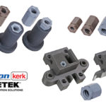
Feature image credit: igus GmbH


Leave a Reply
You must be logged in to post a comment.