• Skip to primary navigation
  • Skip to main content
  • Skip to primary sidebar
  • Skip to footer

Linear Motion Tips

Covering Linear Motion Systems, Components and Linear Motion Resources

  • New
    • Editor’s blog
    • Industry news
    • Motion Casebook
    • Video
  • Applications
  • Slides + guides
    • Ball + roller guides
    • Track roller (cam + wheel) guides
    • Crossed-roller slides
    • Linear bearings
    • Plastic + composite guides
  • Drives
    • Ball + lead + roller screws
    • Belt + chain drives for linear
    • Rack + pinion sets
  • Actuators
    • Ball + leadscrew driven
    • Belt + chain driven
    • Linear motors
    • Mini + piezo + voice coil
    • Rack + pinion driven
    • Rigid-chain actuators
  • Encoders + sensors (linear) + I/O
  • Stages + gantries
  • Suppliers

What are stroke ball splines and how do they differ from standard ball splines?

October 10, 2020 By Danielle Collins Leave a Comment

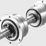
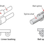
Standard ball splines use balls that recirculate within a nut, or housing, similar to that of a recirculating ball linear bushing. But the mechanisms and geometry required for ball recirculation result in a spline nut that is relatively large in diameter compared to the diameter of the spline shaft.

For a more compact assembly, several manufacturers have developed a type of ball spline — referred to as a stroke ball spline or limited-stroke ball spline — that uses non-recirculating balls. By eliminating recirculation, the nut diameter of a stroke ball spline can be made much smaller than that of standard ball spline.

In a stroke ball spline, rather than recirculating elements, the spline nut uses a ball retainer that contains pockets to hold the balls and ensure they remain in their correct positions. The retainer also ensures proper spacing between the balls. With ball-to-ball contact eliminated, friction is significantly reduced and remains consistent over the entire stroke, so motion is extremely smooth and noise is greatly reduced.

stroke ball splines
Stroke ball splines replace the recirculating mechanisms of standard ball splines with a retainer that holds the balls and ensures their proper spacing.
Image credit: IKO

It’s important to note that because stroke ball splines are designed for low friction, seals are typically not included, so applications that include dust or contamination require that the ball spline be protected by external covers.


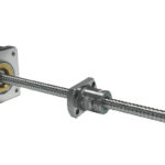
Because compactness is the key feature of stroke ball splines, their size range — indicated by the diameter of the spline shaft — typically runs from just 4 mm up to 16 mm. Smaller spline shaft diameters (4 and 5 mm) have two spline grooves, while larger diameter shafts typically have four grooves.

Similar to the cage in a crossed roller guide, the ball retainer in a stroke ball spline “floats” inside the cylindrical housing, or body. And because the balls don’t recirculate, the travel of a stroke ball spline is limited, with maximum stroke typically around half the overall length of the outer cylinder. And like crossed roller guides, stroke ball splines require occasional full-length strokes to re-center the retainer, as it can “creep” from its centered position, especially in vertical applications or under high-speed operation.

stroke ball splines
Dynamic friction of a standard ball spline (black) and a stroke ball spline (blue).
Image credit: NB Corp.

Stroke ball splines are best suited for applications such as assembly and pick-and-place, where high strokes and torque transfer capabilities are required within a very small footprint. They’re often used, for example, in electronics manufacturing.

stroke ball splines
Image credit: NB Corp.

Because accuracy is extremely important in the many of the target applications for stroke ball splines, manufactures hold relatively tight tolerances for the radial runout and perpendicularity of the spline shaft and mounting surfaces, as well as for the twist, or torsion, of the spline grooves along the length of the shaft. Stroke ball splines are also commonly supplied with a small amount of preload to eliminate clearance and ensure accurate positioning in the rotary direction.

You may also like:

  • ball screw spline
    What’s the difference between a ball screw spline and a…

  • Tips for mounting linear ball bearings: Pillow block housings

  • What options are there for integrated motor and screw designs?
  • crossed roller guides
    Why are cages used in crossed roller guides?
  • ball spline
    When should you use a ball spline?

Filed Under: Ball + roller guides, FAQs + basics, Featured, Slides + guides (all)

Reader Interactions

Leave a Reply Cancel reply

You must be logged in to post a comment.

Primary Sidebar

MOTION DESIGN GUIDES

“motion

“motion

“motion

“motion

“motion

“motion
Subscribe Today

RSS Featured White Papers

  • Identifying Best-Value Linear Motion Technologies
  • What are dual-motion hybrid actuators and where do they excel?
  • Considerations for adding Linear Guide Features to Industrial equipment

RSS Motion Control Tips

  • How to size an electric-motor-driven chain-and-sprocket system
  • New servo drives feature high-power, compact design
  • What are rotary actuators and how do they differ from other rotary tables?
  • What does motor insulation class specify and why is it important?
  • New integrated servo motors from Maxon feature IP65 protection

Follow us on Twitter

Tweets by Linear_Motion

Footer

Linear Motion Tips

Design World Network

Design World Online
The Robot Report
Coupling Tips
Motion Control Tips
Bearing Tips
Fastener Engineering

Linear Motion Tips

Subscribe to our newsletter
Advertise with us
Contact us
About us

Follow us on TwitterAdd us on FacebookAdd us on LinkedInAdd us on YouTubeAdd us on Instagram

Copyright © 2021 · WTWH Media LLC and its licensors. All rights reserved.
The material on this site may not be reproduced, distributed, transmitted, cached or otherwise used, except with the prior written permission of WTWH Media.

Privacy Policy